ICGOO在线商城 > 连接器,互连器件 > 重载连接器 - 触头 > VN02 016 0015 1

 Datasheet下载
- 型号: VN02 016 0015 1
- 制造商: Amphenol
- 库位|库存: xxxx|xxxx
- 要求:
| 数量阶梯 | 香港交货 | 国内含税 |
| +xxxx | $xxxx | ¥xxxx |
查看当月历史价格
查看今年历史价格
VN02 016 0015 1产品简介:
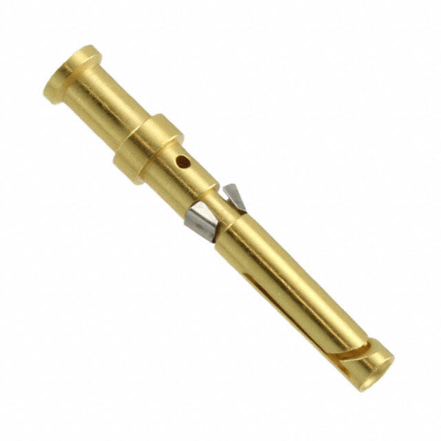
ICGOO电子元器件商城为您提供VN02 016 0015 1由Amphenol设计生产,在icgoo商城现货销售,并且可以通过原厂、代理商等渠道进行代购。 VN02 016 0015 1价格参考。AmphenolVN02 016 0015 1封装/规格:重载连接器 - 触头, Contact Crimp Socket 16-20 AWG Silver。您可以下载VN02 016 0015 1参考资料、Datasheet数据手册功能说明书,资料中有VN02 016 0015 1 详细功能的应用电路图电压和使用方法及教程。
Amphenol Sine Systems Corp是一家专业生产高性能连接器的公司,其产品广泛应用于工业、能源、交通等领域。型号为VN02 016 0015 1的重载连接器触头,主要应用于需要高可靠性和高电流传输能力的工业设备中。

该触头通常用于重载连接器系统中,作为电力和信号传输的关键部件。其应用场景包括但不限于:

1. 工业自动化设备:用于PLC控制柜、伺服驱动系统、机器人等设备中,实现稳定电力与信号连接。
2. 能源与基础设施:应用于风力发电、太阳能逆变器系统、电力配电柜等,确保恶劣环境下电力的高效传输。
3. 交通运输设备:如轨道交通车辆、重型卡车和工程机械,用于连接照明、控制系统和动力模块。
4. 重型机械:用于起重机、挖掘设备、自动化生产线等,满足高振动、高灰尘环境下的连接需求。

该触头具备良好的导电性、耐磨损性和抗腐蚀性,能够在高温、高湿、振动等恶劣条件下稳定工作,是保障设备持续运行的重要组件。
| 参数 | 数值 |
| 产品目录 | |
| 描述 | SOCKET CONTACT 100PCS重负荷电源连接器 C146D Female Contact 20-16 AWG Bag of 100 |
| 产品分类 | |
| 品牌 | Amphenol Tuchel |
| 产品手册 | |
| 产品图片 | |
| rohs | 符合RoHS无铅 / 符合限制有害物质指令(RoHS)规范要求 |
| 产品系列 | 重负荷电源连接器,Amphenol Tuchel VN02 016 0015 1heavymate®,C146 D, M |
| 数据手册 | |
| 产品型号 | VN02 016 0015 1 |
| 产品种类 | 重负荷电源连接器 |
| 产品类型 | Contacts |
| 其它名称 | VN0201600151 |
| 包装 | 散装 |
| 商标 | Amphenol Tuchel |
| 工厂包装数量 | 100 |
| 引脚或插座 | 插口 |
| 插入/联系人性别 | Female |
| 标准包装 | 1 |
| 端接类型 | Crimp |
| 类型 | 带印记 |
| 系列 | Heavymate |
| 线规 | 16-20 AWG |
| 线规量程 | 20-16 |
| 触头端接 | 压接 |
| 触头镀层 | 银 |
| 触头镀层厚度 | - |
| 触点材料 | Brass |
| 触点电镀 | Silver |
| 配用 | /product-detail/zh/C146%2010B064%20005%202/C146%2010B064%20005%202-ND/4502622/product-detail/zh/C146%2010B064%20060%202/C146%2010B064%20060%202-ND/3916323/product-detail/zh/C146%2010B064%20000%202/C146%2010B064%20000%202-ND/3916321/product-detail/zh/C146%2010B040%20060%202/C146%2010B040%20060%202-ND/3916315/product-detail/zh/C146%2010B040%20000%202/C146%2010B040%20000%202-ND/3916314/product-detail/zh/C146%2010B025%20060%202/C146%2010B025%20060%202-ND/3916310/product-detail/zh/C146%2010B025%20005%202/C146%2010B025%20005%202-ND/3916308/product-detail/zh/C146%2010B025%20000%202/C146%2010B025%20000%202-ND/3916307/product-detail/zh/C146%2010B015%20000%202/C146%2010B015%20000%202-ND/3916281/product-detail/zh/C146%2010B008%20000%202/C146%2010B008%20000%202-ND/3916269/product-detail/zh/C146%2010B007%200002C/C146%2010B007%200002C-ND/3916266/product-detail/zh/C146%2010B007%20000%202/C146%2010B007%20000%202-ND/3916265 |


- 商务部:美国ITC正式对集成电路等产品启动337调查
- 曝三星4nm工艺存在良率问题 高通将骁龙8 Gen1或转产台积电
- 太阳诱电将投资9.5亿元在常州建新厂生产MLCC 预计2023年完工
- 英特尔发布欧洲新工厂建设计划 深化IDM 2.0 战略
- 台积电先进制程称霸业界 有大客户加持明年业绩稳了
- 达到5530亿美元!SIA预计今年全球半导体销售额将创下新高
- 英特尔拟将自动驾驶子公司Mobileye上市 估值或超500亿美元
- 三星加码芯片和SET,合并消费电子和移动部门,撤换高东真等 CEO
- 三星电子宣布重大人事变动 还合并消费电子和移动部门
- 海关总署:前11个月进口集成电路产品价值2.52万亿元 增长14.8%
PDF Datasheet 数据手册内容提取
Amphenol Amphenol-Tuchel Electronics GmbH | heavy mate ® Heavy Duty Connectors www.industrial-amphenol.com
Note from the CEO Ladies and Gentlemen, For over 75 years Amphenol has enjoyed success as the interconnection technology provider of choice to industry-leading companies around the world. One of our key stra- tegic areas of focus has been and is the Industrial market. Our organization works with leading manufacturers across a wide range of applications - including Energy Generation & Distribution, Transportation, Heavy Equipment, Factory Automation, Wireless Outdoor, ChipCard Readers - enabling smarter, faster and better technologies to connect pro- ducts to customer solutions. The Industrial market footprint of Amphenol covers over facilities in more than 12 different European countries and more than 30 countries worldwide. Our successful expansion into new regions as well as new industrial applications is a direct reflection of our agile, entrepreneurial management team and our unwavering commitment to execu- te Amphenol‘s strategies for the benefit of our customers, shareholders and employees. Thank you for partnering with Amphenol. Our entire organization is at your service. R. Adam Norwitt President and CEO, Amphenol Corporation 2
Make use of the best Use our global resources “Think global, act local!” Independently from where you are in Europe, we offer you our global expertise and great variety of products and technologies. And in comfort with your personal contact. Our numerous European offices are your access to our global resources. OOUURR OOFFFFIICCEESS IINN EEUURROOPPEE AANNDD WWOORRLLDDWWIIDDEE FFRRAANNCCEE CCHHIINNAA AAUUSSTTRRAALLIIAA SSOOUUTTHH AAFFRRIICCAA GGEERRMMAANNYY KKOORREEAA MMEEXXIICCOO IINNDDIIAA UUNNIITTEEDD KKIINNGGDDOOMM TTAAIIWWAANN UUSSAA IITTAALLYY 3
SECURITY, RELIABILITY AND COMFORTABLE SERVICE FROM ONE SOURCE. 4
More time for important things: benefit from our service and diversity Enjoy security, reliability and comfortable service from one source. INDUSTRIAL@AMPHENOL offers one of the most individual and most diversified service programmes in the market – exclusively for industrial customers. Access all possibilities of the Amphenol group through your personal expert adviser. WWIIDDEE PPRROODDUUCCTT RRAANNGGEE EEXXCCLLUUSSIIVVEENNEESSSS AANNDD FFLLEEXXIIBBIILLIITTYY Take advantage of a choice of Amphenol products. Our broad One face to the customer: every inquiry is handled on an individual product portfolio offers individual solutions from more than 85 service level by your personal key account service partner. This member companies in the global Amphenol group. ensures maximum transparency and best-in-class flexibility in the whole process. QQUUAALLIITTYY IINNDDIIVVIIDDUUAALL SSOOLLUUTTIIOONNSS Interconnect systems need reliability, speed and flawless data Your project requires an individual solution that is not available off- transmission. We continuously test and guarantee the required the-shelf? As your think tank and discussion partner we provide standard in our products – and also in our personal services. engineering support and solution-oriented development for your tailor-made Amphenol product. SSPPEEEEDD AANNDD AAVVAAIILLAABBIILLIITTYY GGLLOOBBAALL KKEEYY AACCCCOOUUNNTT SSEERRVVIICCEE Smart and intelligent processes are the secret behind our service Our key account service is your individual entrance to global programme. Flexible planning and distribution, perfect logistics and know-how, products and services. More than 85 Amphenol highest availability are our key factors for best customer service. companies around the world offer an extensive range of technologies and products. We offer access to our worldwide resources through one individual contact person. 5
| heavy mate® is a Modular Metal Connector Line | What is heavy mate® ? heavy|mate® is a modular connector line, consisting of: • Hoods & Housings • Inserts • Contacts | Why heavy mate® ? • Connections in harsh industrial environment • Robust design necessary • High number of poles or different kinds of signals transmitted • Very good EMC protection required • Power and signal transmission outdoor • Very save locking system required 6
for Applications in Industrial Environments. Major product features • Hybrid interconnections • Good costs • Voltage up to 1000V • VDE, UL, CSA approvals • Vibration proof • High current • Signal transmission • High pole sizes • IP65 to IP68 • Corrosion resistance • Robust | What can heavy mate® offer? • Connectors for industrial applications indoor & outdoor • A wide range of inserts for signal and power transmission • A large variety in pole sizes from 3 up to 280 poles per connector • Current ratings up to 250A per contacts and voltages up to 1000V • A modular connector system to configure customized solutions 7
| How to select a solution with series heavy mate®. Theory • Select an insert that meets your requirements. • Choose the related contacts if not included in inserts. • Choose related housings. • Choose related cable gland. • If you are interested in a cable assembly, please ask us. Practice 1 Requirements • 250V • 5A • 60 contacts • Termination: crimp Solution • Check: Make a pre-selection on the overview page of the series, s. p. 10/11 Possible series: heavy|mate® D, DD and M • Check: Details on the overview pages of the sub-series, see pages 22, 38, 114 All 3 variants are possible; Selection heavy|mate® D • Check: Contact inserts on the detail page of the sub-series Selection: C146 10A064 000 2 • Check: Contacts on the same double page Selection: VN01 016 0002 1 • Check: Housings via crosslink at contact inserts Selection: C146 21R024 600 8 • Check: Gland bushing via crosslink at housings Selection: VN16 320 0126X 8
Practice 2 Requirements • 3 x 400V; 50A; 6mm² wire gauge • 8 x 250V; 8A; 1.5mm² wire gauge • 5 x 400V; 15A; 4mm² wire gauge Solution • Check: Make a pre-selection on the overview page of the series, see pages 10/11 Possible series: heavy|mate® M • Check: How 16 contacts can be realized, see modules overview on page 118 Possible selection: a) 1 x 20 contacts b) 2 x 10 contacts c) 1 x 10 contacts + 1 x 5 contacts d) 1 x 3 contacts + 1 x 5 contacts + 1 x 10 contacts • Check: Technical parameters / solution, see detail pages of the modules on page 126 Possible selection: a) not possible due to voltage b) not possible due to voltage c) not possible due to current d) POSSIBLE • Check: Choose matching contact, see detail page of the modules on page 126 Possible selection: a) C146 A03 001 E8 – VN01 036 0002 1C b) C146 A0 001 E8 – VN01 025 0033 1C c) C146 A10 001 E8 – VN01 016 0027 1XC • Check: Choose matching frame, see frames on page 124 Solution: C146 P10 001 G8 • Check: Choose matching housing, see housings on page 162 Solution: C146 21R010 600 8 9
| Make your selection out of the heavy mate® series! Series A D DD E EE E /FE / KO F Characteristic page 14 page 22 page 38 page 44 page 62 page 68 page 74 Voltage • • • • • • • 250V • • • • • 400V • • • 500V • 690V • 830V 1000V Current • • • • • • • 10A • • • • 16A • 35A • 80A 100A 200A Numbers of contacts Modules for 3 7 24 6 10 6 3 4 8 42 10 18 10 6 10 15 72 16 32 16 8 16 25 108 24 46 24 12 40 17 64 20 Termination • • • • • Crimp • • • Screw • Tension spring Cross reference list see www.amphenol.de/xref/ 10
HSE HvE K M Q Housings Accessories Series page 94 page 98 page 108 page 114 page 156 page 162 page 223 Characteristic Voltage • • • • • 250V • • • • • 400V • • • • 500V • • • 690V • • 830V • 1000V Current • • • • • 10A • • • • • 16A • • • 35A • • 80A • 100A • 200A Modules for Numbers of contacts 6 3+2 4 / 0 1 5 6+2 4 / 2 2 7 10+2 6 /36 3 16+2 4 5 10 20 Termination • • • Crimp • • • Screw Tension spring 11
| The highlights of the series heavy mate®. Contact technology • Turned contacts, which correspond to the market standard. • Turned female contacts of copper for higher current-carrying capacity – specifically for the modular system heavy|mate® M. • Radsok contact technology: These are laminated contacts with very low transition resistance, suitable for high current applications. • Stamped contacts with high performance for semi-automatic processing at great cost savings. • Selectively coated gold plating stamped contacts offer great savings. Housings Surface coatings available in two versions: Flexible cable entry in Standard or High-End with a different positions salt mist resisttaannccee uupp ttttoooooooo – possible on request. 500 hours. Tightness classes in IP65, IP67 or IP68! Robust metal levers in 1 and 2 locking- Quality lever-system. EMC solutions. 12
Modular system With the new series heavy|mate® F Amphenol offers a new modular system that is compatible with the market leader. With the series heavy|mate® M Amphenol offers a system with many benefits: • More module slots in the connector. • Large selection of contact-safe male contacts • Stamped contacts and the Radsok contact technology • Great cost savings potential 13
| heavy mate® A • Rated voltage 250 / 400 V • Rated current 14 A ... 18 A • Termination: screw • Number of contacts: 3, 4, 10, 16, 32 14
heavy|mate® A Brief information Approvals, Testhouse Characteristics Approval-Number SEV 250 V, 10 A UL 600 V, 14 A E 63093 CSA 600 V, 10 A; 16 A; 20 A LR 700721 In general approvals refer to representative versions of the connector series. Extent and specification of tests upon request. 15
heavy|mate® A General information General information • For series heavy|mate® A connectors may be engaged or • Low and high profile housing for heavy|mate® A series inserts for disengaged when live but without electrical load. 10 and 16 contacts. If these connectors are used as plug and socket device, the load shall be reduced to 10 % of the rated current. No standard for this series, but: • Interchangeable with other makes Housings are designed according to DIN EN 175 301 - 801 a) contact insert to contact insert b) contact insert to housing 10 ,16 contacts First-to-mate last-to-break protective ground contact Range of housings Size A3/4 Size A10 Size A16 16
heavy|mate® A Characteristics contact inserts General Characteristics Standard Value Number of contacts 3/4 + 10 + 16 + 32 + Termination technique screw Wire gauge 0.25 - 2.5 mm2 Flammability UL 94 V-0 Electrical Characteristics Rated voltage IEC 60664-1 400 V 250 V Pollution degree IEC 60664-1 3 Installation (overvoltage) category IEC 60664-1 III Material group IEC 60664-1 III b Rated impulse withstand voltage IEC 60664-1 4 KV Current carrying capacity IEC 60512-5-2 see derating curves Rated current T = 40 °C 18 A 16 A 14 A 14 A amp Contact resistance IEC 60512-2-1 ≤ 5 m Ω Insulation resistance IEC 60512-3-1 ≥ 1010 Ω Climatical Characteristics Climatic category IEC 60068-1 40 / 100 / 21 Upper temperature IEC 60512-11-9 + 100 °C Lower temperature IEC 60512-11-10 - 40 °C Mechanical Characteristics IP-degree of protection pin insert 1) IEC 60529 unmated IP00 mated IP20 IP-degree of protection socket insert 1) IEC 60529 unmated IP20 mated IP20 Weight pin insert 13 g 48 g 68 g 136 g Weight socket insert 13 g 52 g 73 g 146 g Mechanical operation IEC 60512-9-1 ≥ 500 mating cycles Materials Insert PA PBT PBT PBT Contacts Cu Zn (brass) Contact plating Ag (silver) IP-degree of protection on termination side of screw version IP 10 17
heavy|mate® A Contact inserts 3 - 4 + | Size A3/4 | 400 V/10 A Housings from page 162 Description Part Number Drawing Figure Contact insert 3 + Male insert C146 10A003 002 4 for screw termination Female insert C146 10B003 002 4 for screw termination Pin layout Male insert Female insert Description Part Number Drawing Figure Contact insert 4 + Male insert C146 10A004 002 4 for screw termination Female insert C146 10B004 002 4 for screw termination Pin layout Male insert Female insert Derating curves Curve Wire gauge a 1.5 mm2 b 2.5 mm2 18
heavy|mate® A Contact inserts 10 + | Size A10 | 250 V/16 A Housings from page 162 Description Part Number Drawing Figure Contact insert 10 + Male insert C146 10A010 002 4 for screw termination Male insert C146 10A010 102 4 with wire protection for screw termination Female insert C146 10B010 002 4 for screw termination Female insert C146 10B010 102 4 with wire protection for screw termination Pin layout Assembly instruction Male insert Female insert Panel cut out (insert) Derating curves Curve Wire gauge a 1.5 mm2 b 2.5 mm2 19
heavy|mate® A Contact inserts 16 + |Size A16 | 250 V/16 A Housings from page 162 Description Part Number Drawing Figure Contact insert 16 + Male insert C146 10A016 002 4 for screw termination Male insert C146 10A016 102 4 with wire protection for screw termination Female insert C146 10B016 002 4 for screw termination Female insert C146 10B016 102 4 with wire protection for screw termination Pin layout Assembly instruction Male insert Female insert Panel cut out (insert) Derating curves Curve Wire gauge a 1.5 mm2 b 2.5 mm2 20
heavy|mate® A Contact inserts 2x16 + PE | Size A10 | 250 V/16 A Housings from page 162 Description Part Number Drawing Figure Contact insert 32 + Male insert C146 10A016 002 4 (1 - 16) for screw termination + C146 10A016 004 4 (17 - 32) Male insert C146 10A016 102 4 (1 - 16) with wire protection + for screw termination C146 10A016 104 4 (17 - 32) Female insert C146 10B016 002 4 (1 - 16) for screw termination + C146 10B016 004 4 (17 - 32) Female insert C146 10B016 102 4 (1 - 16) with wire protection + for screw termination C146 10B016 104 4 (17 - 32) Pin layout Assembly instruction Male insert Female insert Panel cut out (insert) Derating curves Curve Wire gauge a 1.5 mm2 b 2.5 mm2 21
| heavy mate® D • Rated voltage 250 V • Rated current 10 A ... 16 A • Termination: crimp • Number of contacts: 7, 15, 25, 40, 50, 64, 128 22
heavy|mate® D Brief information Approvals, Testhouse Characteristics Approval-Number SEV 250 V, 10 A UL 600 V, 14 A E 63093 600 V, 15 A (high current) CSA 600 V, 10 A 48932 In general approvals refer to representative versions of the connector series. Extent and specification of tests upon request. 23
heavy|mate® D General information General information • Contact inserts without crimp contacts, crimping tools see • For contact inserts for turned contacts, guide pins and guide separate catalogue „Tools“. socket are recommended (see page 226). • Contacts must be ordered separately, processing instructions • By using contact inserts with two PE-connections without hoods, it see catalogue „Tools“. is necessary to connect the facing of each PE-connection. • We recommend using the high profile housings / hoods for the • If connectors are mounted in non conductive housings both heavy|mate® D inserts. protective earthing terminals shall be mounted. • Connectors series heavy|mate® D may be engaged or disengaged when live but without electrical load. If these connectors are mated or unmated under load, the load shall be reduced to 10 % of the rated current. Standardised connectorsaccording to DIN EN 175 301 - 801 (DIN 43652) Interchangeable with all other products which are according to the standard. a) Contact insert to contact insert 15, 25, 40, 64 way. b) Contact insert to housing 15, 25, 40, 64 way. High protection against mismating First-to-mate last-to-break protective ground contact • Female inserts with funnel shaped contact entry avoids mismating with stamped contacts. Restricted entry Contact inserts for stamped contacts and for turned contacts Range of housings Size A3/4 Size A10 Size A16 Size E16 Size E24 Size E48 24
heavy|mate® D General information Modified contact arrangement for rated voltages of 400 V (15) ➛ 7 + (25) ➛ 11 + (40) ➛ 20 + (64) ➛ 32 + full load contact unoccupied Removal of contacts, front releas stamped male contacts stamped female contacts all turned contacts 25
heavy|mate® D Characteristics contact inserts General Characteristics Standard Value Number of contacts 7 15 25 40 50 64 128 2x25 2x64 Contact arrangement DIN EN 175 301-801 (DIN 43652) • • • • Termination technique crimp, wire wrap Max. wire diameter 4.1 mm Flammability UL 94 V-0 Electrical Characteristics Rated voltage 1) IEC 60664-1 250 V~ (400 V~ 2)) (600 V UL / CSA 3)) Pollution degree IEC 60664-1 3 Installation (overvoltage) category IEC 60664-1 III Material group IEC 60664-1 III b Rated impulse withstand voltage IEC 60664-1 4 kV Rated current IEC 60512-5-2 see derating curves Rated current T = 40 °C 16 A 12 A 12 A 10 A 10 A 10 A 10 A amp Insulation resistance IEC 60512-3-1 ≥ 1010 Ω Climatical Characteristics Climatic category IEC 60068-1 40/125/21 Upper temperature IEC 60512-11-9 + 125°C Lower temperature IEC 60512-11-10 - 40°C Mechanical Characteristics IP-degree of protection pin insert IEC 60529 unmated IP00 mated IP20 IP-degree of protection socket insert IEC 60529 unmated IP20 mated IP20 Weight pin insert 8 g 28 g 34 g 53 g 68 g 65 g 130 g Weight socket insert 8 g 30 g 38 g 64 g 76 g 82 g 164 g Mechanical operation IEC 60512-9-1 ≥ 500 mating cycles Materials Insert IEC 60664-1 PBTP PC GV 4) Colour insert IEC 60664-1 grey 1) Restriction for 8 contacts in metal housing see page 27 2) Modified contact arrangement, see 26 page 25 3) Label for CSA application see page 228 4) Polycarbonat-glas fibre filled
heavy|mate® D Contact inserts 7 + , 8 pol | Size A3/4 | 250 V/10 A Housings from page 162 Description Part Number Drawing Figure Contact insert 7 + , 42 V~ in metal housings/250 V in thermoplastic housings (Please order contacts separately, see page 34) Male insert C146 10A007 000 2 for stamped crimp contacts Male insert C146 10A007 500 2 for turned crimp contacts Female insert C146 10B007 000 2 for stamped crimp contacts Female insert C146 10B007 500 2 for turned crimp contacts Pin layout Male insert 7+ Female insert Protective earthing contact preleading Description Part Number Drawing Figure Contact insert 8, 42 V~ in metal housings/250 V in thermoplastic housings (Please order contacts separately, see page 34) Male insert C146 10A008 000 2 for stamped crimp contacts Male insert C146 10A008 500 2 for turned crimp contacts Female insert C146 10B008 000 2 for stamped crimp contacts Female insert C146 10B008 500 2 for turned crimp contacts Pin layout (Note: For use up to 42 V~, the PE contact can be used as regular contact.) Male insert Female insert 8/PE Derating curves Stamped contacts Turned contacts Curve Wire gauge Curve Wire gauge a 0.5 mm2 a 0.5 mm2 b 1.5 mm2 & b 1.5 mm2 2.5 mm2 c 2.5 mm2 c 1.5 mm2 - 2.5 mm2 (High current) 27
heavy|mate® D Contact inserts 15 + | Size A10 | 250 V/10 A Housings from page 162 Description Part Number Drawing Figure Contact insert 15 + (Please order contacts separately, see page 34) Male insert C146 10A015 000 2 for stamped crimp contacts Male insert C146 10A015 500 2 for turned crimp contacts Female insert C146 10B015 000 2 for stamped crimp contacts Female insert C146 10B015 500 2 for turned crimp contacts Contact insert 15 + , 2 x PE-termination (Please order contacts separately, see page 34) Male insert C146 10A015 060 2 for stamped crimp contacts Female insert C146 10B015 060 2 for stamped crimp contacts Pin layout Assembly instruction Male insert Female insert Panel cut out (insert) Derating curves Stamped contacts Turned contacts Curve Wire gauge Curve Wire gauge a 0.5 mm2 a 0.5 mm2 b 1.5 mm2 b 1.5 mm2 c 2.5 mm2 c 2.5 mm2 d 1.5 mm2 - 2.5 mm2 (High current) 28
heavy|mate® D Contact inserts 25 + | Size A16 | 250 V/10 A Housings from page 162 Description Part Number Drawing Figure Contact insert 25 + (Please order contacts separately, see page 34) Male insert C146 10A025 000 2 for stamped crimp contacts Male insert C146 10A025 500 2 for turned crimp contacts Female insert C146 10B025 000 2 for stamped crimp contacts Female insert C146 10B025 500 2 for turned crimp contacts Contact insert 25 + , 2 x PE-termination (Please order contacts separately, see page 34) Male insert C146 10A025 060 2 for stamped crimp contacts Female insert C146 10B025 060 2 for stamped crimp contacts Pin layout Assembly instruction Male insert Female insert Panel cut out (insert) Derating curves Stamped contacts Turned contacts Curve Wire gauge Curve Wire gauge a 0.5 mm2 a 0.5 mm2 b 1.5 mm2 b 1.5 mm2 c 2.5 mm2 c 2.5 mm2 d 1.5 mm2 - 2.5 mm2 (High current) 29
heavy|mate® D Contact inserts 40 + | Size E16 | 250 V/10 A Housings from page 162 Description Part Number Drawing Figure Contact insert 40 + (Please order contacts separately, see page 34) Male insert C146 10A040 000 2 for stamped crimp contacts Male insert C146 10A040 500 2 for turned crimp contacts Female insert C146 10B040 000 2 for stamped crimp contacts Female insert C146 10B040 500 2 for turned crimp contacts Contact insert 40 + , 2 x PE-termination (Please order contacts separately, see page 34) Male insert C146 10A040 060 2 for stamped crimp contacts Female insert C146 10B040 060 2 for stamped crimp contacts Pin layout Assembly instruction Male insert Female insert Panel cut out (insert) Derating curves Stamped contacts Turned contacts Curve Wire gauge Curve Wire gauge a 0.5 mm2 a 0.5 mm2 b 1.5 mm2 b 1.5 mm2 c 2.5 mm2 c 2.5 mm2 d 1.5 mm2 (High current) e 2.5 mm2 (High current) 30
heavy|mate® D Contact inserts 50 + | Size A32 | 250 V/10 A Housings from page 162 Description Part Number Drawing Figure Contact insert 50 + (Please order contacts separately, see page 34) Male insert C146 10A025 000 2 for stamped crimp contacts + C146 10A025 005 2 Male insert C146 10A025 500 2 for turned crimp contacts + C146 10A025 505 2 Female insert C146 10B025 000 2 for stamped crimp contacts + C146 10B025 005 2 Female insert C146 10B025 500 2 for turned crimp contacts + C146 10B025 505 2 Pin layout Assembly instruction Male insert Female insert Panel cut out (insert) Derating curves Stamped contacts Turned contacts Curve Wire gauge Curve Wire gauge a 0.5 mm2 a 0.5 mm2 b 1.5 mm2 b 1.5 mm2 c 2.5 mm2 c 2.5 mm2 d 1.5 mm2 (High current) e 2.5 mm2 (High current) 31
heavy|mate® D Contact inserts 64 + | Size E24 | 250 V/10 A Housings from page 162 Description Part Number Drawing Figure Contact insert 64 + (Please order contacts separately, see page 34) Male insert C146 10A064 000 2 for stamped crimp contacts Male insert C146 10A064 500 2 for turned crimp contacts Female insert C146 10B064 000 2 for stamped crimp contacts Female insert C146 10B064 500 2 for turned crimp contacts Contact insert 64 + , 2 x PE-termination (Please order contacts separately, see page 34) Male insert C146 10A064 060 2 for stamped crimp contacts Female insert C146 10B064 060 2 for stamped crimp contacts Pin layout Assembly instruction Male insert Female insert Panel cut out (insert) Derating curves Stamped contacts Turned contacts Curve Wire gauge Curve Wire gauge a 0.5 mm2 a 0.5 mm2 b 1.5 mm2 b 1.5 mm2 c 2.5 mm2 c 2.5 mm2 d 1.5 mm2 (High current) e 2.5 mm2 (High current) 32
heavy|mate® D Contact inserts 128 + | Size E48 | 250 V/10 A Housings from page 162 Bezeichnung Bestellnummer Maßzeichnung Abbildung Contact insert 128 + (Please order contacts separately, see page 34) Male insert C146 10A064 000 2 for stamped crimp contacts + C146 10A064 005 2 Male insert C146 10A064 500 2 for turned crimp contacts + C146 10A064 505 2 Female insert C146 10B064 000 2 for stamped crimp contacts + C146 10B064 005 2 Female insert C146 10B064 500 2 for turned crimp contacts + C146 10B064 505 2 Pin layout Assembly instruction Male insert Female insert Panel cut out (insert) Derating curves Stamped contacts Turned contacts Curve Wire gauge Curve Wire gauge a 0.5 mm2 a 0.5 mm2 b 1.5 mm2 b 1.5 mm2 c 2.5 mm2 c 2.5 mm2 d 1.5 mm2 (High current) e 2.5 mm2 (High current) 33
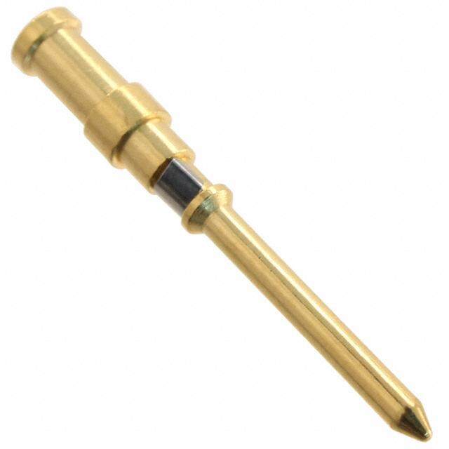
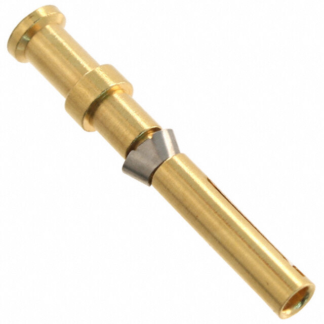
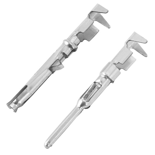
heavy|mate® D Crimp technology Large range of wire gauges .N01 016 0003 (1) .N01 016 0002 (1) .N01 016 0005 (1) Gas-tight (coldwelding) 0.14 0.25 0.5 0.5 1.0 1.5 1.5 2.5 Stamped crimp contacts with insulation crimp, to absorbe mechanical stress from the crimped connection Insulation grip Mechanical retention spring stop on female and male contact Female contact Male contact High current carrying capacity Example single contact Curve a: 2.5 mm2 Standard contact. wire gauge Curve a: 2.5 mm2 High current contact, wire gauge 34
heavy|mate® D Characteristics crimp contacts Stamped crimp contacts Electrical Characteristics Contact resistance IEC 60512-2-1 ≤ 5 m Ω Climatical Characteristics Upper temperature IEC 60512-11-9 + 125 °C Lower temperature IEC 60512-11-10 - 40 °C Mechanical Characteristics Mechanical operation IEC 60512-9-1 ≥ 500 mating cycles Materials Male contact Cu Zn (brass) Female contact Cu Sn (tin bronce) Contact plating Ag (silver) / Au (gold) Turned crimp contacts Electrical Characteristics Contact resistance IEC 60512-2-1 ≤ 5 m Ω Climatical Characteristics Upper temperature IEC 60512-11-9 + 100 °C Lower temperature IEC 60512-11-10 - 40 °C Mechanical Characteristics Mechanical operation IEC 60512-9-1 ≥ 500 mating cycles Materials Male contact Cu Zn (brass) Female contact Cu Zn (brass) Contact plating Ag (silver) / Au (gold) 35
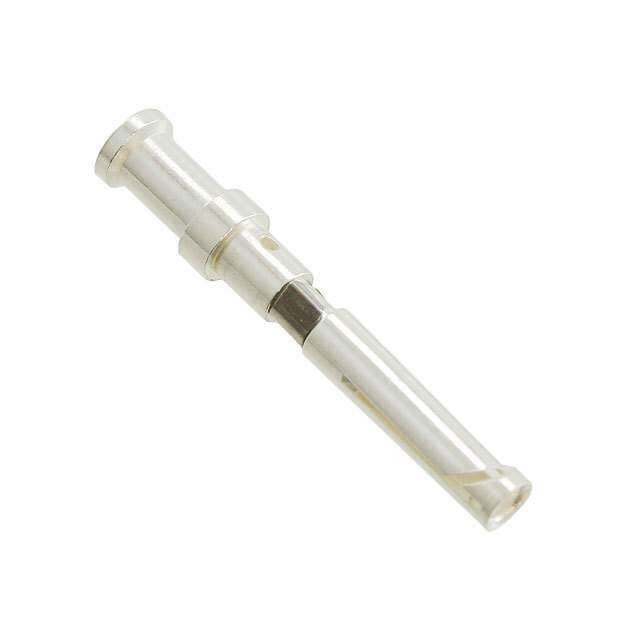
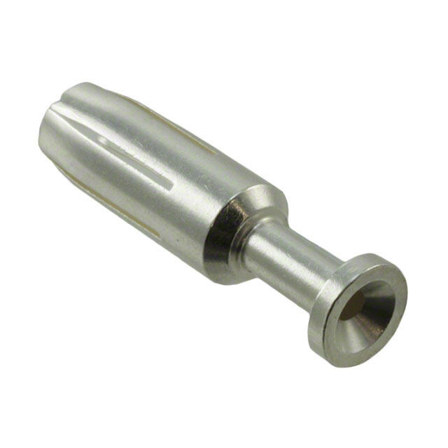
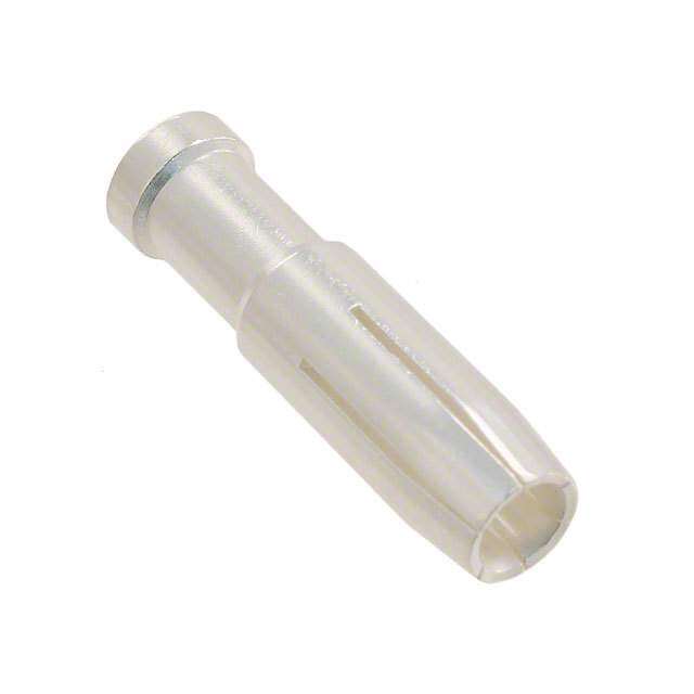
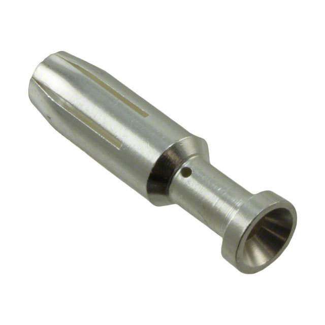
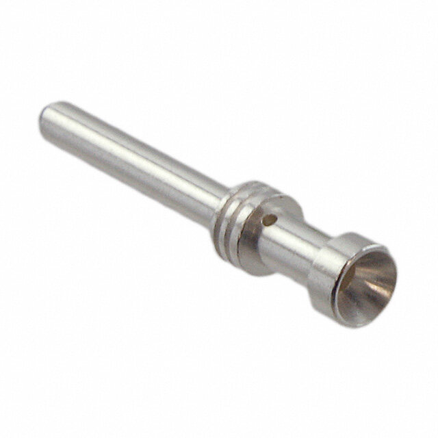
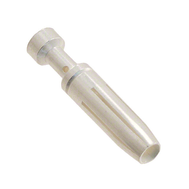
heavy|mate® D Stamped crimp contacts Supplied as for wire gauge AWG Pieces Part Number Figure Male contact Female contact Stamped single contacts silver plating 0.14 - 0.5 mm2 26 - 20 100 VN01 016 0003 (1) VN02 016 0003 (1) standard 0.5 - 1.5 mm2 20 - 16 100 VN01 016 0002 (1) VN02 016 0002 (1) 1.5 - 2.5 mm2 16 - 14 100 VN01 016 0005 (1) VN02 016 0005 (1) silver plating 0.5 - 1.5 mm2 20 - 16 100 VN01 016 0015 (1) VN02 016 0015 (1) high current 1.5 - 2.5 mm2 16 - 14 100 VN01 016 0016 (1) VN02 016 0016 (1) gold plating 0.14 - 0.5 mm2 26 - 20 100 VN01 016 0003 (2) VN02 016 0003 (2) standard 0.5 - 1.5 mm2 20 - 16 100 VN01 016 0002 (2) VN02 016 0002 (2) 1.5 - 2.5 mm2 16 - 14 100 VN01 016 0005 (2) VN02 016 0005 (2) Stamped Contacts on reel for hand crimp tools silver plating 0.14 - 0.5 mm2 26 - 20 200 ZN01 016 0003 (1) ZN02 016 0003 (1) standard 0.5 - 1.5 mm2 20 - 16 200 ZN01 016 0002 (1) ZN02 016 0002 (1) 1.5 - 2.5 mm2 16 - 14 200 ZN01 016 0005 (1) ZN02 016 0005 (1) silver plating 0.5 - 1.5 mm2 20 - 16 200 ZN01 016 0015 (1) ZN02 016 0015 (1) high current 1.5 - 2.5 mm2 16 - 14 100 ZN01 016 0016 (1) ZN02 016 0016 (1) gold plating 0.14 - 0.5 mm2 26 - 20 200 ZN01 016 0003 (2) ZN02 016 0003 (2) standard 0.5 - 1.5 mm2 20 - 16 200 ZN01 016 0002 (2) ZN02 016 0002 (2) 1.5 - 2.5 mm2 16 - 14 200 ZN01 016 0005 (2) ZN02 016 0005 (2) Stamped contacts on reel for crimp machines contact feeding left hand side silver plating 0.14 - 0.5 mm2 26 - 20 2000 TN01 016 0003 (1) TN02 016 0003 (1) standard 0.5 - 1.5 mm2 20 - 16 2000 TN01 016 0002 (1) TN02 016 0002 (1) 1.5 - 2.5 mm2 16 - 14 2000 TN01 016 0005 (1) TN02 016 0005 (1) silver plating 0.5 - 1.5 mm2 20 - 16 2000 TN01 016 0015 (1) TN02 016 0015 (1) high current 1.5 - 2.5 mm2 18 - 14 2000 TN01 016 0016 (1) TN02 016 0016 (1) gold plating 0.14 - 0.5 mm2 26 - 20 2000 TN01 016 0003 (2) TN02 016 0003 (2) standard 0.5 - 1.5 mm2 20 - 16 2000 TN01 016 0002 (2) TN02 016 0002 (2) 1.5 - 2.5 mm2 16 - 14 2000 TN01 016 0005 (2) TN02 016 0005 (2) Tools for stamped crimp contacts Description for wire gauge Part Number Contact locator Crimping dies Tool Removal tool for contacts - - - FG 0300 146 1 Service crimping tool 0.14 - 0.5 mm2 - - TA 0100 146 0.5 - 1.5 mm2 Crimping tool 0.14 - 0.5 mm2 TA 0001 146 000 1 TA 0000 202 TA 0000 for single contacts 0.5 - 1.5 mm2 TA 0002 146 000 1 TA 0000 163 TA 0500 1.5 - 2.5 mm2 TA 0007 146 000 3 TA 0000 141 Further tools see catalogue "Tools" 36 Stripping length see page 249-251
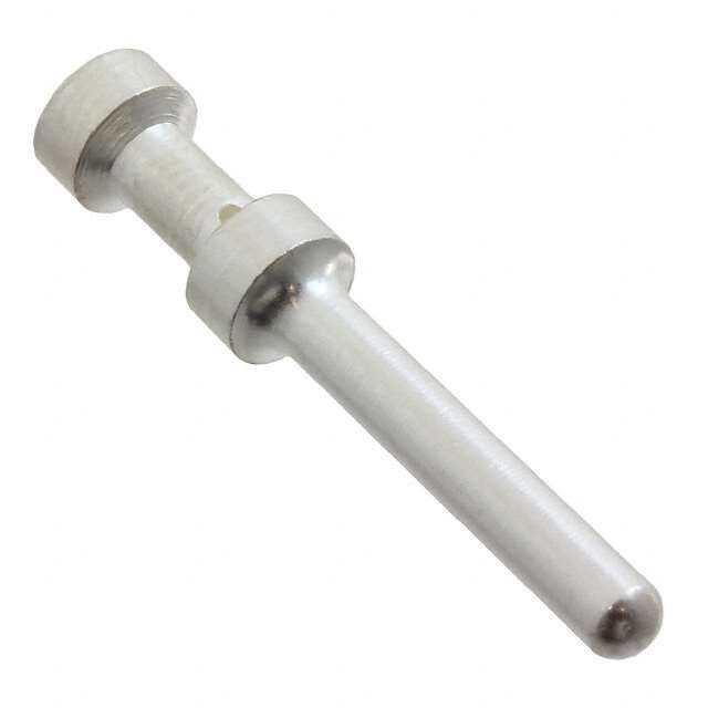
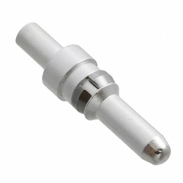
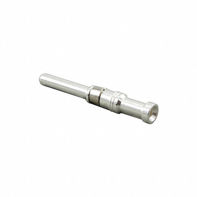
heavy|mate® D Turned crimp contacts Supplied as for wire gauge AWG Pieces Part Number Figure Male contact Female contact Turned crimp contacts single contact silver plating 0.14 - 0.37 mm2 26 - 22 100 VN01 016 0024 (1)C VN02 016 0024 (1)C 0.5 mm2 20 100 VN01 016 0025 (1)C VN02 016 0025 (1)C 0.75 - 1.0 mm2 20 - 16 100 VN01 016 0026 (1)C VN02 016 0026 (1)C 1.5 mm2 16 - 15 100 VN01 016 0027 (1)C VN02 016 0027 (1)C 2.5 mm2 14 100 VN01 016 0028 (1)C VN02 016 0028 (1)C gold plating 0.14 - 0.37 mm2 26 - 22 100 VN01 016 0024 (2)C VN02 016 0024 (2)C 0.5 mm2 20 100 VN01 016 0025 (2)C VN02 016 0025 (2)C 0.75 - 1.0 mm2 20 - 16 100 VN01 016 0026 (2)C VN02 016 0026 (2)C 1.5 mm2 16 - 15 100 VN01 016 0027 (2)C VN02 016 0027 (2)C 2.5 mm2 14 100 VN01 016 0028 (2)C VN02 016 0028 (2)C Tools for turned crimp contacts Description for wire gauge Part Number Contact locator Crimping dies Tool Removal tool for contacts - - - FG 0300 146 1 Service crimping tool 0.14 - 0.5 mm2 - - TA 0100 146 0.5 - 1.5 mm2 Further tools see catalogue "Tools" 37
| heavy mate® DD • Rated voltage 250 V • Rated current 8 A ... 9 A • Termination: crimp • Number of contacts: 24, 42, 72, 108 38
heavy|mate® DD Brief information Approvals, Testhouse Characteristics Approval-Number SEV 250 V, 10 A UL 600 V, 8,5 A E 63093 CSA 600 V, 10 A LR 700721 In general approvals refer to representative versions of the connector series. Extent and specification of tests upon request. 39
hheeaavvyy||mmaattee®® DDDD Characteristics contact inserts General Characteristics Standard Value Number of contacts 24 + 42 + 72 + 108 + Termination technique crimp Wire gauge 0.14 mm2 - 2.5 mm2 Flammability UL 94 V-0 Electrical Characteristics Rated voltage IEC 60664-1 250 V (600 V UL / CSA) Pollution degree IEC 60664-1 2 (3 mated and locked) Installation (overvoltage) category IEC 60664-1 III Material group IEC 60664-1 III b Rated impulse withstand voltage IEC 60664-1 4 kV Current carrying capacity IEC 60512-5-2 see derating curves Contact resistance IEC 60512-2-1 ≤ 5 m Ω Insulation resistance IEC 60512-3-1 ≥ 1010 Ω Climatical Characteristics Climatic category IEC 60068-1 40 / 100 / 21 Upper temperature IEC 60512-11-9 + 100 °C Lower temperature IEC 60512-11-10 - 40 °C Mechanical Characteristics Weight pin insert 44 g 50 g 63 g 86 g IP-degree of protection pin insert IEC 60529 unmated IP00 mated IP20 IP-degree of protection socket insert IEC 60529 unmated IP20 mated IP20 Weight socket insert 41 g 50 g 67 g 88 g Mechanical operation IEC 60512-9-1 > 500 mating cycles Materials Insert PBTP Colour insert grey Contacts CuZn (brass) Contact plating Ag (silver) Derating curves 24 + 42 + Curve Wire gauge Curve Wire gauge a 0.75 mm2 a 0.75 mm2 b 1.5 mm2 b 1.5 mm2 72 + 108 + Curve Wire gauge Curve Wire gauge a 0.75 mm2 a 0.75 mm2 b 1.5 mm2 b 1.5 mm2 40
heavy|mate® DD Contact inserts 24 - 72 + | 250 V/10 A Housings from page 162 Description Part Number Drawing Figure Contact insert 24 + for turned contacts Size E 6 (Please order contacts separately, see page 43) Male insert C146 10A024 000 9 for turned crimp contacts Female insert C146 10B024 000 9 for turned crimp contacts Contact insert 42 + for turned contacts Size E 10 (Please order contacts separately, see page 43) Male insert C146 10A042 000 9 for turned crimp contacts Female insert C146 10B042 000 9 for turned crimp contacts Contact insert 72 + for turned contacts Size E 16 (Please order contacts separately, see page 43) Male insert C146 10A072 000 9 for turned crimp contacts Female insert C146 10B072 000 9 for turned crimp contacts 41
heavy|mate® DD Contact inserts 108 - 216 + | 250 V/10 A Housings from page 162 Description Part Number Drawing Figure Contact insert 108 + for turned contacts Size E 24 (Please order contacts separately, see page 43) Male insert C146 10A108 000 9 for turned crimp contacts Female insert C146 10B108 000 9 for turned crimp contacts Contact insert 216 + for turned contacts Size E 48 (Please order contacts separately, see page 43) Male insert C146 10A108 000 9 for turned crimp contacts + C146 10A108 005 9 Female insert C146 10B108 000 9 for turned crimp contacts + C146 10B108 005 9 Pin layout Assembly instruction Male insert Female insert Panel cut out (insert) 42
heavy|mate® DD Crimp contacts Supplied as for wire gauge AWG Pieces Part Number Figure Male contact Female contact Turned crimp contacts single contact 1.6mm silver plating 0.14 - 0,37 mm2 26 - 22 100 VN01 016 0024 (1)C VN02 016 0024 (1)C 0.5 mm2 20 100 VN01 016 0025 (1)C VN02 016 0025 (1)C 0.75 - 1,0 mm2 20 - 16 100 VN01 016 0026 (1)C VN02 016 0026 (1)C 1.5 mm2 16 - 15 100 VN01 016 0027 (1)C VN02 016 0027 (1)C 2.5 mm2 14 100 VN01 016 0028 (1)C VN02 016 0028 (1)C gold plating 0.14 - 0.37 mm2 26 - 22 100 VN01 016 0024 (2)C VN02 016 0024 (2)C 0.5 mm2 20 100 VN01 016 0025 (2)C VN02 016 0025 (2)C 0.75 - 1.0 mm2 20 - 16 100 VN01 016 0026 (2)C VN02 016 0026 (2)C 1.5 mm2 16 - 15 100 VN01 016 0027 (2)C VN02 016 0027 (2)C 2.5 mm2 14 100 VN01 016 0028 (2)C VN02 016 0028 (2)C Tools for turned crimp contacts Description for wire gauge Part Number Contact locator Crimping dies Tool Removal tool for contacts - - - FG 0300 146 1 Service crimping tool 0.14 - 0.5 mm2 - - TA 0100 146 0.5 - 1.5 mm2 Further tools see catalogue “Tools” Stripping length see page 249-251 43
| heavy mate® E • Rated voltage 500 V • Rated current 16 A ... 22 A • Termination: screw, crimp, tension spring • Numbers of contacts: 6, 10, 16, 24, 48 44
heavy|mate® E Brief information Approvals, Testhouse Characteristics Approval-Number SEV 400 V, 16 A UL 600 V, 16 A E 63093 CSA 600 V, 16 A 48932 In general approvals refer to representative versions of the connector series. Extent and specification of tests upon request. 45
heavy|mate® E General information General information • Contact inserts without crimp contacts. • Crimping tools and processing instructions see separate catalogue • Connectors series heavy|mate® E may be engaged or disengaged „Tools“. when live but without electrical load. If these connectors are mated • Low and high profile housings are usable. or unmated under load, the load shall be reduced to 10 % of the • If wire ferrule are used, screw terminals without rated current. wire protection are preferred. No standard for this series, but: Interchangeable with other products Housings are designed according to DIN EN 175 301 - 801 a) contact insert to contact insert 6, 10, 16, 24 contacts b) contact insert to housing 6, 10 ,16, 24 contacts First-to-mate last-to-break protective ground contact Contact inserts for screw termination, screw termination with wire protection and for crimp termination Screw termination Screw termination with wire protection Crimp termination Range of housings Size E6 Size E10 Size E16 Size E24 Size E48 46
heavy|mate® E Characteristics contact inserts General Characteristics Standard Value Number of contacts 6 + 10 + 16 + 24 + 48 + Termination technique crimp / screw / tension spring Wire gauge 0.5 - 4 mm2 Flammability UL 94 V-0 Electrical Characteristics Rated voltage IEC 60664-1 max. 500 V (600 V UL / CSA 1)) Pollution degree IEC 60664-1 3 Material group IEC 60664-1 III b Installation (overvoltage) category IEC 60664-1 III Rated impulse withstand voltage IEC 60664-1 6,0 kV Current carrying capacity IEC 60512-5-2 see derating curves Rated current T = 40 °C 22 A 19 A 19 A 18 A 18 A amp Contact resistance IEC 60512-2-1 < 5 mΩ Insulation resistance IEC 60512-3-1 ≥ 1010 Ω Climatical Characteristics Climatic category IEC 60068-1 40 / 125 / 21 Upper temperature IEC 60512-11-9 + 125 °C Lower temperature IEC 60512-11-10 - 40°C Mechanical Characteristics IP-degree of protection pin insert 2) IEC 60529 unmated IP00 mated IP20 IP-degree of protection socket insert 2) IEC 60529 unmated IP20 mated IP20 Weight: male insert crimp (for stamped contacts) 33 g 39 g 45 g 55 g 110 g female insert crimp (for stamped contacts) 33 g 39 g 49 g 62 g 124 g male insert screw 43 g 57 g 78 g 105 g 210 g female insert screw 43 g 57 g 78 g 106 g 212 g Mechanical operation IEC 60512-9-1 > 500 mating cycles Materials Insert PC GV (Polycarbonat) Colour insert grey Screw contacts CuZn (brass) Contact plating Ag (silver) / Au (gold) 1) Label for CSA application see page 228 47 2) IP-degree of protection on ter mination side of screw version IP 10
heavy|mate® E Contact inserts 6 + | Size E6 | 500 V/16 A Housings from page 162 Description Part Number Drawing Figure Screw termination Male insert C146 10A006 002 1 for screw termination Male insert C146 10A006 102 1 with wire protection for screw termination Female insert C146 10B006 002 1 for screw termination Female insert C146 10B006 102 1 with wire protection for screw termination Tension spring Male insert C146 10A006 400 1 with Tension spring Female insert C146 10B006 400 1 with Tension spring Stamped crimp contacts (Please order contacts separately, see page 58) Male insert C146 10A006 000 1 for stamped crimp contacts Female insert C146 10B006 000 1 for stamped crimp contacts 48
heavy|mate® E Contact inserts 6 + | Size E6 | 500 V/16 A Housings from page 162 Description Part Number Drawing Figure Turned crimp contacts (Please order contacts separately, see page 58) Male insert C146 10A006 500 1 for turned crimp contacts Female insert C146 10B006 500 1 for turned crimp contacts Pin layout Assembly instruction Male insert Female insert Panel cut out (insert) Derating curves Stamped contacts Turned contacts Screw termination Curve a: 1.5 mm2 wire gauge Curve b: 2.5 mm2 wire gauge 49
heavy|mate® E Contact inserts 10 + | Size E10 | 500 V/16 A Housings from page 162 Description Part Number Drawing Figure Screw termination Male insert C146 10A010 002 1 for screw termination Male insert C146 10A010 102 1 with wire protection for screw termination Female insert C146 10B010 002 1 for screw termination Female insert C146 10B010 102 1 with wire protection for screw termination Tension spring Male insert C146 10A010 400 1 with Tension spring Female insert C146 10B010 400 1 with Tension spring Stamped crimp contacts (Please order contacts separately, see page 58) Male insert C146 10A010 000 1 for stamped crimp contacts Female insert C146 10B010 000 1 for stamped crimp contacts 50
heavy|mate® E Contact inserts 10 + | Size E10 | 500 V/16 A Housings from page 162 Description Part Number Drawing Figure Turned crimp contacts (Please order contacts separately, see page 58) Male insert C146 10A010 500 1 for turned crimp contacts Female insert C146 10B010 500 1 for turned crimp contacts Pin layout Assembly instruction Male insert Female insert Panel cut out (insert) Derating curves Stamped contacts Turned contacts Screw termination Curve a: 1.5 mm2 wire gauge Curve b: 2.5 mm2 wire gauge 51
heavy|mate® E Contact inserts 16 + | Size E16 | 500 V/16 A Housings from page 162 Description Part Number Drawing Figure Screw termination Male insert C146 10A016 002 1 for screw termination Male insert C146 10A016 102 1 with wire protection for screw termination Female insert C146 10B016 002 1 for screw termination Female insert C146 10B016 102 1 with wire protection for screw termination Tension spring Male insert C146 10A016 400 1 with Tension spring Female insert C146 10B016 400 1 with Tension spring Stamped crimp contacts (Please order contacts separately, see page 58) Male insert C146 10A016 000 1 for stamped crimp contacts Female insert C146 10B016 000 1 for stamped crimp contacts 52
heavy|mate® E Contact inserts 16 + | Size E16 | 500 V/16 A Housings from page 162 Description Part Number Drawing Figure Turned crimp contacts (Please order contacts separately, see page 58) Male insert C146 10A016 500 1 for turned crimp contacts Female insert C146 10B016 500 1 for turned crimp contacts Pin layout Assembly instruction Male insert Female insert Panel cut out (insert) Derating curves Stamped contacts Turned contacts Screw termination Curve a: 1.5 mm2 wire gauge Curve b: 2.5 mm2 wire gauge 53
heavy|mate® E Contact inserts 24 + | Size E24 | 500 V/16 A Housings from page 162 Description Part Number Drawing Figure Screw termination Male insert C146 10A024 002 1 for screw termination Male insert C146 10A024 102 1 with wire protection for screw termination Female insert C146 10B024 002 1 for screw termination Female insert C146 10B024 102 1 with wire protection for screw termination Tension spring Male insert C146 10A024 400 1 with Tension spring Female insert C146 10B024 400 1 with Tension spring Stamped crimp contacts (Please order contacts separately, see page 58) Male insert C146 10A024 000 1 for stamped crimp contacts Female insert C146 10B024 000 1 for stamped crimp contacts 54
heavy|mate® E Contact inserts 24 + | Size E24 | 500 V/16 A Housings from page 162 Description Part Number Drawing Figure Turned crimp contacts (Please order contacts separately, see page 58) Male insert C146 10A024 500 1 for turned crimp contacts Female insert C146 10B024 500 1 for turned crimp contacts Pin layout Assembly instruction Male insert Female insert Panel cut out (insert) Derating curves Stamped contacts Turned contacts Screw termination Curve a: 1.5 mm2 wire gauge Curve b: 2.5 mm2 wire gauge 55
heavy|mate® E Contact inserts 48 + | Size E48 | 500 V/16 A Housings from page 162 Description Part Number Drawing Figure Screw termination Male insert C146 10A024 002 1 for screw termination + C146 10A024 002 1 Male insert C146 10A024 102 1 with wire protection + for screw termination C146 10A024 102 1 Female insert C146 10B024 002 1 for screw termination + C146 10B024 002 1 Female insert C146 10B024 102 1 with wire protection + for screw termination C146 10B024 102 1 Stamped crimp contacts (Please order contacts separately, see page 58) Male insert C146 10A024 000 1 for stamped crimp contacts + C146 10A024 005 1 Female insert C146 10B024 000 1 for stamped crimp contacts + C146 10B024 005 1 Turned crimp contacts (Please order contacts separately, see page 58) Male insert C146 10A024 500 1 for turned crimp contacts + C146 10A024 505 1 Female insert C146 10B024 500 1 for turned crimp contacts + C146 10B024 505 1 56
heavy|mate® E Kontakteinsätze 48 + | Baugröße E48 | 500 V/16 A Housings from page 162 Pin layout Assembly instruction Male insert Female insert Panel cut out (insert) Derating curves Stamped contacts Turned contacts Screw termination Curve a: 1.5 mm2 wire gauge Curve b: 2.5 mm2 wire gauge 57
heavy|mate® E Crimp technology Large range of wire gauges N01 025 0001 (1) N01 025 0010 (1) Gas-tight (coldwelding) 0,5 1,0 1,5 1,5 2,5 Stamped crimp contacts with insulation crimp, to absorbe mechanical stress from the crimped connection Insulation grip Mechanical retention spring stop on female and male contact Female contact Male contact High current carrying capacity Example single contact Curve a: 2.5 mm2 wire gauge 58
heavy|mate® E Characteristics crimp contacts Stamped crimp contacts Electrical Characteristics Contact resistance IEC 60512-2-1 < 5 m Ω Mechanical Characteristics Mechanical operation IEC 60512-9-1 ≥ 500 mating cycles Materials Male contact Cu Zn (brass) Female contact Cu Sn (tin bronce) Contact plating Ag (silver) / Au (gold) Turned crimp contacts Electrical Characteristics Contact resistance IEC 60512-2-1 ≤ 5 m Ω Climatical Characteristics Upper temperature IEC 60512-11-9 + 125 °C Lower temperature IEC 60512-11-10 - 40 °C Mechanical Characteristics Mechanical operation IEC 60512-9-1 ≥ 500 mating cycles Materials Male contact Cu Zn (brass) Female contact Cu Zn (brass) Contact plating Ag (silver) / Au (gold) 59
heavy|mate® E Stamped crimp contacts Supplied as for wire gauge AWG Pieces Part Number Figure Male contact Female contact Stamped single contacts silver plating 0.5 - 1.5 mm2 20 - 16 100 VN01 025 0001 (101) VN02 025 0001 (101) 1.5 - 2.5 mm2 16- 14 100 VN01 025 0010 (101) VN02 025 0010 (101) gold plating 0.5 - 1.5 mm2 20 - 16 100 VN01 025 0001 (102) VN02 025 0001 (102) 1.5 - 2.5 mm2 16- 14 100 VN01 025 0010 (102) VN02 025 0010 (102) Stamped Contacts on reel for hand crimp tools silver plating 0.5 - 1.5 mm2 20 - 16 200 ZN01 025 0001 (1) ZN02 025 0001 (1) 1.5 - 2.5 mm2 16 - 14 100 ZN01 025 0010 (1) ZN02 025 0010 (1) gold plating 0.5 - 1.5 mm2 20 - 16 200 ZN01 025 0001 (2) ZN02 025 0001 (2) 1.5 - 2.5 mm2 16 - 14 100 ZN01 025 0010 (2) ZN02 025 0010 (2) Stamped contacts on reel for crimp machines contact feeding left hand side silver plating 0.5 - 1.5 mm2 20 - 16 2000 TN01 025 0001 (1) TN02 025 0001 (1) 1.5 - 2.5 mm2 16 - 14 2000 TN01 025 0010 (1) TN02 025 0010 (1) Tools for turned crimp contacts Description for wire gauge Part Number Contact locator Crimping dies Tool Removal tool for contacts - - - FG 0200 146 1 Crimping tool for stamped 0.5 - 1.5 mm2 TA 0004 146 000 1 TA 0000 163 TA 0000 single contacts 1.5 - 2.5 mm2 TA 0005 146 000 3 TA 0000 141 4-indent crimping tool 0.5 - 4.0 mm2 - - TB 0600 146 for turned contacts Further tools see catalogue “Tools” 60 Stripping length see page 249-251
heavy|mate® E Turned crimp contacts Supplied as for wire gauge AWG Pieces Part Number Figure Male contact Female contact Turned crimp contacts single contact silver plating 0.5 mm2 20 100 VN01 025 0035 (1)C VN02 025 0035 (1)C 0.75 - 1.0 mm2 18 100 VN01 025 0036 (1)C VN02 025 0036 (1)C 1.5 mm2 16 100 VN01 025 0037 (1)C VN02 025 0037 (1)C 2.5 mm2 14 100 VN01 025 0038 (1)C VN02 025 0038 (1)C 4.0 mm2 12 100 VN01 025 0039 (1)C VN02 025 0039 (1)C gold plating 0.5 mm2 20 100 VN01 025 0035 (2)C VN02 025 0035 (2)C 0.75 - 1.0 mm2 18 100 VN01 025 0036 (2)C VN02 025 0036 (2)C 1.5 mm2 16 100 VN01 025 0037 (2)C VN02 025 0037 (2)C 2.5 mm2 14 100 VN01 025 0038 (2)C VN02 025 0038 (2)C 4.0 mm2 12 100 VN01 025 0039 (2)C VN02 025 0039 (2)C Tools for turned crimp contacts Description for wire gauge Part Number Contact locator Crimping dies Tool Removal tool for contacts FG 0300 146 7 Crimping tool for stamped 0.5 - 2.5 mm2 TA 0010 146 000 6 TA 0000 144 TA 0000 single contacts 4 mm2 TA 0010 146 000 7 TA 0000 124 TA 0500 4-indent crimping tool TB 0600 146 for turned contacts Further tools see catalogue “Tools” 61
| heavy mate® EE • Rated voltage 500 V (600 V UL / CSA) • Rated current 16 A • Termination: crimp • Numbers of contacts: 10, 18, 32, 46 62
heavy|mate® EE Brief information Approvals, Testhouse Characteristics Approval-Number UL 600 V, 15 A E 63093 CSA 600 V, 16 A 172062-1027396 (LR 48323-2) In general approvals refer to representative versions of the connector series. Extent and specification of tests upon request. 63
hheeaavvyy||mmaattee®® EEEE Characteristics contact inserts General Characteristics Standard Value Number of contacts 10 + 18 + 32 + 46 + Termination technique crimp Wire gauge 0.5 mm2 - 4.0 mm2 Flammability UL 94 V-0 Electrical Characteristics Rated voltage IEC 60664-1 500 V (600 V UL / CSA) Pollution degree IEC 60664-1 3 Installation (overvoltage) category IEC 60664-1 III Material group IEC 60664-1 III b Rated impulse withstand voltage IEC 60664-1 6 kV Current carrying capacity IEC 60512-5-2 see derating curves Contact resistance IEC 60512-2-1 ≤ 5 m Ω Insulation resistance IEC 60512-3-1 ≥ 1010 Ω Climatical Characteristics Climatic category IEC 60068-1 40 / 100 / 21 Upper temperature IEC 60512-11-9 + 100 °C Lower temperature IEC 60512-11-10 - 40 °C Mechanical Characteristics Mechanical operation IEC 60512-9-1 > 500 mating cycles IP-degree of protection pin insert IEC 60529 unmated IP00 mated IP20 IP-degree of protection socket insert IEC 60529 unmated IP20 mated IP20 Materials Insert PC Colour insert grey Contacts CuZn (brass) Contact plating Ag (silver) / Au (gold) Derating curves 10 + 18 + Curve Wire gauge Curve Wire gauge a 0.5 mm2 a 0.5 mm2 b 2.5 mm2 b 2.5 mm2 c 4.0 mm2 c 4.0 mm2 32 + 46 + Curve Wire gauge Curve Wire gauge a 0.5 mm2 a 0.5 mm2 b 2.5 mm2 b 2.5 mm2 c 4.0 mm2 c 4.0 mm2 64
heavy|mate® EE Contact inserts 10 - 18 + | 500 V/15 A Housings from page 162 Description Part Number Drawing Figure Contact insert10 + Size E 6 (Please order contacts separately, see page 67) Male insert C146 10A010 500 10 for turned crimp contacts Female insert C146 10B010 500 10 for turned crimp contacts Pin layout Assembly instruction Male insert Female insert Panel cut out (insert) 8 64 1 1 46 8 9 2 2 9 10 75 3 3 57 10 Description Part Number Drawing Figure Contact insert 18 + Size E 10 (Please order contacts separately, see page 67) Male insert C146 10A018 500 10 for turned crimp contacts Female insert C146 10B018 500 10 for turned crimp contacts Pin layout Assembly instruction Male insert Female insert Panel cut out (insert) 10 6 610 14 1 1 14 15 2 2 15 16 3 3 16 17 4 4 17 18 5 5 18 13 9 913 65
heavy|mate® EE Contact inserts 32 - 46 + | 500 V/16 A Housings from page 162 Description Part Number Drawing Figure Contact insert 32 + Size E 16 (Please order contacts separately, see page 67) Male insert C146 10A032 500 10 for turned crimp contacts Female insert C146 10B032 500 10 for turned crimp contacts Pin layout Assembly instruction Male insert Female insert Panel cut out (insert) 1710 1017 24 1 1 24 25 2 2 25 26 3 3 26 27 4 4 27 28 5 5 28 29 6 6 29 30 7 7 30 31 8 8 31 32 9 9 32 2316 1623 Description Part Number Drawing Figure Contact insert 46 + Size E 24 (Please order contacts separately, see page 67) Male insert C146 10A046 500 10 for turned crimp contacts Female insert C146 10B046 500 10 for turned crimp contacts Pin layout Assembly instruction Male insert Female insert Panel cut out (insert) 2414 1424 34 1 1 34 35 2 2 35 36 3 3 36 37 4 4 37 38 5 5 38 39 6 6 39 40 7 7 40 41 8 8 41 42 9 9 42 43 10 10 43 44 11 11 44 45 12 12 45 46 3323 13 13 2333 46 66
heavy|mate® EE Crimp contacts Supplied as for wire gauge AWG Pieces Part Number Figure Male contact Female contact Turned crimp contacts single contact 2.5mm silver plating 0.5 mm2 20 100 VN01 025 0035 (1)C VN02 025 0035 (1)C 0.75 - 1.0 mm2 18 100 VN01 025 0036 (1)C VN02 025 0036 (1)C 1.5 mm2 16 100 VN01 025 0037 (1)C VN02 025 0037 (1)C 2.5 mm2 14 100 VN01 025 0038 (1)C VN02 025 0038 (1)C 4.0 mm2 12 100 VN01 025 0039 (1)C VN02 025 0039 (1)C gold plating 0.5 mm2 20 100 VN01 025 0035 (2)C VN02 025 0035 (2)C 0.75 - 1.0 mm2 18 100 VN01 025 0036 (2)C VN02 025 0036 (2)C 1.5 mm2 16 100 VN01 025 0037 (2)C VN02 025 0037 (2)C 2.5 mm2 14 100 VN01 025 0038 (2)C VN02 025 0038 (2)C 4.0 mm2 12 100 VN01 025 0039 (2)C VN02 025 0039 (2)C Tools for turned crimp contacts Description for wire gauge Part Number Contact locator Crimping dies Tool Removal tool for contacts FG 0300 146 7 Crimping tool for stamped 0.5 - 2.5 mm2 TA 0010 146 000 6 TA 0000 144 TA 0000 single contacts 4 mm2 TA 0010 146 000 7 TA 0000 124 TA 0500 4-indent crimping tool TB 0600 146 for turned contacts Further tools see catalogue “Tools” Stripping length see page 249-251 67
| heavy mate® E / FE / KO • Rated voltage 400 V • Material contacts: iron-constantan • Rated current 10 A • Number of contacts: 6, 10, 16, 24 68
heavy|mate® E / FE / KO Brief information 69
heavy|mate® E / FE / KO General information Connectors with iron (FE) and constantan (CO) contacts are basically used in measuring and control circuits to serve as Amphenol’s Industial Connectors with iron (FE) an Contantan interface between FE/CO thermocouples and control unit, i. e. (CO) contacts are used to connect FE/CO thermocouples with temperature control of moulds in injection moulding machines. electronic signal amplifiers in measuring and control circuits, i. e. for Through the use of FE/CO connectors in the thermocouple circuit temperature control of moulding machines. the measuring results are more accurate, thus the tolerance of the temperature control is much narrower. Errors with various combinations The connection of unlike metals (FE/Brass and CO/Brass) generate thermoelectric voltage errors in the mesuring circuit caused by the flow from iron wire to the brass contact or by temperature changes at the contact elements. Contact without Thermo Contacts with Thermo Contacts Material Nominal Temp. MS/FE MS/KO FE/FE KO/KO 100 °C + 4 % - 16 % - 4 % - 2 % 200 °C + 2.5 % - 8 % - 3 % - 1.5 % 300 °C + 1.3 % - 12.7 % - 1.3 % 0 % 400 °C + 1.5 % - 4.5 % - 1.0 % 0 % By using FE/CO contacts respectively these deviations will be minimized. Material / Temperature Range Temperatur range Material/measurement procedure < 150 °C any/Resistance measurement 150 °C - 450 °C FE-CO (iron/Constantan) 450 °C - approx. 1000 °C Ni/Cr-Ni (Nickel/Chrome/Nickel) Temperature changes cause errors Nominale Ambient temperature mV/°C Temp.°C 70
heavy|mate® E / FE / KO Characteristics contact inserts General Characteristics Standard Value Number of contacts 6 + 10 + 16 + 24 + Termination technique screw Wire gauge 0.25 mm2 - 2.5 mm2 Flammability UL 94 V-0 Electrical Characteristics Rated voltage IEC 60664-1 500 V Pollution degree IEC 60664-1 3 Installation (overvoltage) category IEC 60664-1 III Material group IEC 60664-1 III b Current carrying capacity IEC 60664-1 6 kV Rated current T = 40 °C 10 A amp Contact resistance IEC 60512-2-1 ≤ 10 m Ω Insulation resistance IEC 60512-3-1 ≥ 1010 Ω Climatical Characteristics Climatic category IEC 60068-1 40 / 100 / 21 Upper temperature IEC 60512-11-9 + 100 °C Lower temperature IEC 60512-11-10 - 40 °C Mechanical Characteristics IP-degree of protection pin insert 1) IEC 60529 unmated IP00 mated IP20 IP-degree of protection socket insert 1) IEC 60529 unmated IP20 mated IP20 Weight pin insert 45 g 60 g 78 g 105 g Weight socket insert 45 g 60 g 78 g 105 g Mechanical operation IEC 60512-9-1 ≥ 100 mating cycles Materials Insert PA, GV (Polyamid) Colour insert grey Contacts iron; gal cd 4 constantan = without plating 1) IP-degree of protection on ter mination side of screw version IP 10 71
heavy|mate® E / FE / KO Contact inserts 6 - 10 + Housings from page 162 Description Part Number Drawing Figure Contact insert 6 + with iron-constantan contacts Male insert C146 10A006 810 1 with wire protection Female insert C146 10B006 810 1 with wire protection Pin layout Assembly instruction Male insert Female insert Panel cut out (insert) Description Part Number Drawing Figure Contact insert 10 + with iron-constantan contacts Male insert C146 10A010 810 1 with wire protection Female insert C146 10B010 810 1 with wire protection Pin layout Assembly instruction Male insert Female insert Panel cut out (insert) 72
heavy|mate® E / FE / KO Contact inserts 16 - 24 + Housings from page 162 Description Part Number Drawing Figure Contact insert 16 + with iron-constantan contacts Male insert C146 10A016 810 1 with wire protection Female insert C146 10B016 810 1 with wire protection Pin layout Assembly instruction Male insert Female insert Panel cut out (insert) Description Part Number Drawing Figure Contact insert 24 + with iron-constantan contacts Male insert C146 10A024 810 1 with wire protection Female insert C146 10B024 810 1 with wire protection Pin layout Assembly instruction Male insert Female insert Panel cut out (insert) 73
| heavy mate® F • Modular connector • Compatible with market standard • Rated voltage up to 830 V • Rated current up to 40 A • Termination: crimp • Numbers of contacts: 2 - 102 74
heavy|mate® F Brief information Approvals, Testhouse Characteristics Approval-Number UL in preparation in preparation CSA in preparation in preparation 75
heavy|mate® F General information General information • Modules inserts without crimp contacts, crimping tools see • We recommend using the high profile housings / hoods for the separate catalogue “Tools”. heavy|mate® F inserts. • Contacts must be ordered separatly, processing instructions see • Empty modul spaces have to be filled with blind modules. catalogue “Tools”. • Torque for PE connection 1.2 Nm • Connectors series heavy|mate® F may be engaged or disengaged when live but without electrical load. If these connectors are mated or unmated under load, the load shall be reduced to 10 % of rated current. Advantages of the system • No standard but interchangeable with competitive products. • Housings are designed according to DIN EN 175 301 801 • Simply connecting of the modules and frames. First-to-mate last-to-break protective ground contact Range of housings Size E6 Size E10 Size E16 Size E24 Size E48 76
heavy|mate® F How to select a solution with series heavy|mate® F? Requirements • 3 x 400V; 50A; 6mm² wire gauge • 8 x 250V; 8A; 1.5mm² wire gauge • 5 x 400V; 15A; 4mm² wire gauge Solution 1. Check how 16 contacts can be realized; see modules overview on page 78 Possible selection: a) 1 x 17 contacts b) 2 x 12 contacts c) 1 x 6 contacts + 1 x 12 contacts d) 1 x 3 contacts + 1 x 6 contacts + 1 x 12 contacts 2. Check technical parameters / solution, see detail pages of the modules from page 82 Possible selection: a) not possible due to voltage b) not possible due to voltage c) not possible due to current d) POSSIBLE 3. Choose matching contact, see detail page of the modules on page 82 Possible selection: a) 3 contacts = C146 10A003 500 15 → contacts = VN01 040 0013 1C b) 6 contacts = C146 10A006 500 15 → contacts = VN01 025 0039 1C c) 12 contacts = C146 10A012 500 15 → contacts = VN01 016 0027 1C 4. Choose matching frame, see frames on page 80 Solution: C146 10P10 000 15 5. Choose matching housing, see housings on page 162 Solution: C146 21R010 600 8 Schematic construction 77
hheeaavvyy||mmaattee®® FF Modules Overview Description Part Number Drawing Figure 3 contacts module for turned contacts, details see page 82 Pin modules C146 10A003 500 15 Socket modules C146 10B003 500 15 6 contacts module for turned contacts, 500V, details see page 84 Pin modules C146 10A006 500 15 Socket modules C146 10B006 500 15 8 contacts module for turned contacts, 400V, details see page 86 Pin modules C146 10A008 500 15 Socket modules C146 10B008 500 15 78 1) If connectors are mounted in non conductive housings both protective earthing terminals shall be mounted.
hheeaavvyy||mmaattee®® FF Modules Overview Description Part Number Drawing Figure 12 contacts module for turned contacts. 250V, details see page 88 Pin modules C146 10A012 500 15 Socket modules C146 10B012 500 15 17 contacts module for turned contacts, 160V, details see page 90 Pin modules C146 10A017 500 15 Socket modules C146 10B017 500 15 20 contacts module for turned contacts 500V, details see page 92 Pin modules C146 10A020 500 15 Socket modules C146 10B020 500 15 1) If connectors are mounted in non conductive housings both protective earthing terminals shall be mounted. 79
heavy|mate® F Frames Housings from page 162 Description Part Number Drawing Figure Frames for 2 modules Frame for pin modules C146 10P006 000 15 Frame for socket modules C146 10S006 000 15 Frames for 3 modules Frame for pin modules C146 10P010 000 15 Frame for socket modules C146 10S010 000 15 Frames for 4 modules Frame for pin modules C146 10P016 000 15 Frame for socket modules C146 10S016 000 15 It is possible to mount socket modules in frames for pin modules (possibility of inverse configuration). 80 1) If connectors are mounted in non conductive housings both protective earthing terminals shall be mounted.
heavy|mate® F Frames Housings from page 162 Description Part Number Drawing Figure Frames for 6 modules Frame for pin modules C146 10P024 000 15 Frame for socket modules C146 10S024 000 15 1) If connectors are mounted in non conductive housings both protective earthing terminals shall be mounted. 81
heavy|mate® F Characteristics 3 contacts module General Characteristics Standard Value Number of contacts 3 Termination technique crimp Wire Gauge 1.5 –6.0 mm² (AWG 16-10) Flammability UL94 V-0 Electrical Characteristics Rated voltage IEC 60664-1 400 V (conductor – earth) 690 V (conductor – conductor) Pollution degree IEC 60664-1 3 Installation (overvoltage) category IEC 60664-1 III Material group IEC 60664-1 II (PA) Rated impulse withstand voltage IEC 60664-1 6 kV Current carrying capacity IEC 60512-5-2 see derating curves Contact resistance IEC 60512-2-1 ≤ 5 mΩ Insulation resistance IEC 60512-3-1 ≥ 1010 Ω Climatical Characteristics Climatic category IEC 60068-1 40/125/21 Upper temperature IEC 60512-11-9 +125°C Lower temperature IEC 60512-11-10 -40°C Mechanical Characteristics Mechanical operation IEC 60512-9-1 ≥500 mating cycles IP-degree of protection IEC 60529 IP00 (pin insert) / IP20 (socket insert) Materials Module PA6.6 GF Colour module black Contact CuZn (brass) Contact plating Ag (silver) / Au (gold) Derating Curves In preparation 82
heavy|mate® F 3 contacts module + crimp contacts Description Part Number Drawing Figure 3 contacts module (Please order contacts separately) Pin module C146 10A003 500 15 Socket module C146 10B003 500 15 Supplied as for wire gauge AWG Pieces Part Number Figure Male contact Female contact Turned 4 mm crimp contacts single contact silver plating 1.5 mm2 16 100 VN01 040 0010 1C VN02 040 0010 1C 2.5 mm2 14 100 VN01 040 0011 1C VN02 040 0011 1C 4 mm2 12 100 VN01 040 0012 1C VN02 040 0012 1C 6 mm2 10 100 VN01 040 0013 1C VN02 040 0013 1C 83
heavy|mate® F Characteristics 6 contacts module General Characteristics Standard Value Number of contacts 6 Termination technique crimp Wire Gauge 0.5 –4.0 mm² (AWG 20-12) Flammability UL94 V-0 Electrical Characteristics Rated voltage IEC 60664-1 500 V Pollution degree IEC 60664-1 3 Installation (overvoltage) category IEC 60664-1 III Material group IEC 60664-1 II (PA) Rated impulse withstand voltage IEC 60664-1 6 kV Current carrying capacity IEC 60512-5-2 see derating curves Contact resistance IEC 60512-2-1 ≤ 5 mΩ Insulation resistance IEC 60512-3-1 ≥ 1010 Ω Climatical Characteristics Climatic category IEC 60068-1 40/125/21 Upper temperature IEC 60512-11-9 +125°C Lower temperature IEC 60512-11-10 -40°C Mechanical Characteristics Mechanical operation IEC 60512-9-1 ≥500 mating cycles IP-degree of protection IEC 60529 IP00 (pin insert) / IP20 (socket insert) Materials Module PA6.6 GF Colour module black Contact CuZn (brass) Contact plating Ag (silver) / Au (gold) Derating Curves In preparation 84
heavy|mate® F 6 contacts module + crimp contacts Description Part Number Drawing Figure 6 contacts module (Please order contacts separately) Pin module C146 10A006 500 15 Socket module C146 10B006 500 15 Supplied as for wire gauge AWG Pieces Part Number Figure Male contact Female contact Turned 2.5 mm crimp contacts single contact silver plating 0.5 mm2 20 100 VN01 025 0035 (1)C VN02 025 0035 (1)C 0.75 - 1.0 mm2 18 100 VN01 025 0036 (1)C VN02 025 0036 (1)C 1.5 mm2 16 100 VN01 025 0037 (1)C VN02 025 0037 (1)C 2.5 mm2 14 100 VN01 025 0038 (1)C VN02 025 0038 (1)C 4.0 mm2 12 100 VN01 025 0039 (1)C VN02 025 0039 (1)C gold plating 0.5 mm2 20 100 VN01 025 0035 (2)C VN02 025 0035 (2)C 0.75 - 1.0 mm2 18 100 VN01 025 0036 (2)C VN02 025 0036 (2)C 1.5 mm2 16 100 VN01 025 0037 (2)C VN02 025 0037 (2)C 2.5 mm2 14 100 VN01 025 0038 (2)C VN02 025 0038 (2)C 4.0 mm2 12 100 VN01 025 0039 (2)C VN02 025 0039 (2)C Tools for turned contacts Description for wire gauge Part Number Contact locator Crimping dies Tool Removal tool for contacts FG 0300 146 7 Crimping tool for turned 0.5 - 2.5 mm2 TA 0010 146 000 6 TA 0000 144 TA 0000 single contacts 4 mm2 TA 0010 146 000 7 TA 0000 124 TA 0500 4-indet crimping tool for TB 0600 146 turned contacts Further tools see catalogue “Tools” 85
heavy|mate® F Characteristics 8 contacts module General Characteristics Standard Value Number of contacts 8 Termination technique crimp Wire Gauge 0.5 – 4.0 mm² (AWG 20-12) Flammability UL94 V-0 Electrical Characteristics Rated voltage IEC 60664-1 400 V Pollution degree IEC 60664-1 3 Installation (overvoltage) category IEC 60664-1 III Material group IEC 60664-1 II (PA) Rated impulse withstand voltage IEC 60664-1 6 kV Current carrying capacity IEC 60512-5-2 see derating curves Contact resistance IEC 60512-2-1 ≤ 5 mΩ Insulation resistance IEC 60512-3-1 ≥ 1010 Ω Climatical Characteristics Climatic category IEC 60068-1 40/125/21 Upper temperature IEC 60512-11-9 +125°C Lower temperature IEC 60512-11-10 -40°C Mechanical Characteristics Mechanical operation IEC 60512-9-1 ≥500 mating cycles IP-degree of protection IEC 60529 IP00 (pin insert) / IP20 (socket insert) Materials Module PA6.6 GF Colour module black Contact CuZn (brass) Contact plating Ag (silver) / Au (gold) Derating Curves In preparation 86
heavy|mate® F 8 contacts module + crimp contacts Description Part Number Drawing Figure 38contacts module (Please order contacts separately) Pin module C146 10A008 500 15 Socket module C146 10B008 500 15 Supplied as for wire gauge AWG Pieces Part Number Figure Male contact Female contact Turned 2.5 mm crimp contacts single contact silver plating 0.5 mm2 20 100 VN01 025 0035 (1)C VN02 025 0035 (1)C 0.75 - 1.0 mm2 18 100 VN01 025 0036 (1)C VN02 025 0036 (1)C 1.5 mm2 16 100 VN01 025 0037 (1)C VN02 025 0037 (1)C 2.5 mm2 14 100 VN01 025 0038 (1)C VN02 025 0038 (1)C 4.0 mm2 12 100 VN01 025 0039 (1)C VN02 025 0039 (1)C gold plating 0.5 mm2 20 100 VN01 025 0035 (2)C VN02 025 0035 (2)C 0.75 - 1.0 mm2 18 100 VN01 025 0036 (2)C VN02 025 0036 (2)C 1.5 mm2 16 100 VN01 025 0037 (2)C VN02 025 0037 (2)C 2.5 mm2 14 100 VN01 025 0038 (2)C VN02 025 0038 (2)C 4.0 mm2 12 100 VN01 025 0039 (2)C VN02 025 0039 (2)C Tools for turned contacts Description for wire gauge Part Number Contact locator Crimping dies Tool Removal tool for contacts FG 0300 146 7 Crimping tool for turned 0.5 - 2.5 mm2 TA 0010 146 000 6 TA 0000 144 TA 0000 single contacts 4 mm2 TA 0010 146 000 7 TA 0000 124 TA 0500 4-indet crimping tool for TB 0600 146 turned contacts Further tools see catalogue “Tools” 87
heavy|mate® F Characteristics 12 contacts module General Characteristics Standard Value Number of contacts 12 Termination technique crimp Wire Gauge 0.14 – 2.5 mm² (AWG 26-14) Flammability UL94 V-0 Electrical Characteristics Rated voltage IEC 60664-1 250 V (conductor – earth) 400 V (conductor – conductor) Pollution degree IEC 60664-1 3 Installation (overvoltage) category IEC 60664-1 III Material group IEC 60664-1 II (PA) Rated impulse withstand voltage IEC 60664-1 4 kV Current carrying capacity IEC 60512-5-2 see derating curves Contact resistance IEC 60512-2-1 ≤ 5 mΩ Insulation resistance IEC 60512-3-1 ≥ 1010 Ω Climatical Characteristics Climatic category IEC 60068-1 40/100/21 Upper temperature IEC 60512-11-9 +100°C Lower temperature IEC 60512-11-10 -40°C Mechanical Characteristics Mechanical operation IEC 60512-9-1 ≥500 mating cycles IP-degree of protection IEC 60529 IP00 (pin insert) / IP20 (socket insert) Materials Module PA6.6 GF Colour module black Contact CuZn (brass) Contact plating Ag (silver) / Au (gold) Derating Curves In preparation 88
heavy|mate® F 12 contacts module + crimp contacts Description Part Number Drawing Figure 12 contacts module (Please order contacts separately) Pin module C146 10A012 500 15 Socket module C146 10B012 500 15 Supplied as for wire gauge AWG Pieces Part Number Figure Male contact Female contact Turned crimp contacts single contact silver plating 0.14 - 0.37 mm2 26 - 22 100 VN01 016 0024 (1)C VN02 016 0024 (1)C 0.5 mm2 20 100 VN01 016 0025 (1)C VN02 016 0025 (1)C 0.75 - 1.0 mm2 20 - 16 100 VN01 016 0026 (1)C VN02 016 0026 (1)C 1.5 mm2 16 - 15 100 VN01 016 0027 (1)C VN02 016 0027 (1)C 2.5 mm2 14 100 VN01 016 0028 (1)C VN02 016 0028 (1)C gold plating 0.14 - 0.37 mm2 26 - 22 100 VN01 016 0024 (2)C VN02 016 0024 (2)C 0.5 mm2 20 100 VN01 016 0025 (2)C VN02 016 0025 (2)C 0.75 - 1.0 mm2 20 - 16 100 VN01 016 0026 (2)C VN02 016 0026 (2)C 1.5 mm2 16 - 15 100 VN01 016 0027 (2)C VN02 016 0027 (2)C 2.5 mm2 14 100 VN01 016 0028 (2)C VN02 016 0028 (2)C Tools for turned contacts Description for wire gauge Part Number Contact locator Crimping dies Tool Removal tool for contacts - - - FG 0300 146 1 Service crimping tool 0.14 - 0.5 mm2 - - TA 0100 146 0.5 - 1.5 mm2 Further tools see catalogue “Tools” 89
heavy|mate® F Characteristics 17 contacts module General Characteristics Standard Value Number of contacts 17 Termination technique crimp Wire Gauge 0.14 –2.5mm² (AWG 26-14) Flammability UL94 V-0 Electrical Characteristics Rated voltage IEC 60664-1 160 V Pollution degree IEC 60664-1 3 Installation (overvoltage) category IEC 60664-1 III Material group IEC 60664-1 II (PA) Rated impulse withstand voltage IEC 60664-1 2.5 kV Current carrying capacity IEC 60512-5-2 see derating curves Contact resistance IEC 60512-2-1 ≤ 5 mΩ Insulation resistance IEC 60512-3-1 ≥ 1010 Ω Climatical Characteristics Climatic category IEC 60068-1 40/100/21 Upper temperature IEC 60512-11-9 +100°C Lower temperature IEC 60512-11-10 -40°C Mechanical Characteristics Mechanical operation IEC 60512-9-1 ≥500 mating cycles IP-degree of protection IEC 60529 IP00 (pin insert) / IP20 (socket insert) Materials Module PA6.6 GF Colour module black Contact CuZn (brass) Contact plating Ag (silver) / Au (gold) Derating Curves In preparation 90
heavy|mate® F 17 contacts module + crimp contacts Description Part Number Drawing Figure 17 contacts module (Please order contacts separately) Pin module C146 10A017 500 15 Socket module C146 10B017 500 15 Supplied as for wire gauge AWG Pieces Part Number Figure Male contact Female contact Turned crimp contacts single contact silver plating 0.14 - 0.37 mm2 26 - 22 100 VN01 016 0024 (1)C VN02 016 0024 (1)C 0.5 mm2 20 100 VN01 016 0025 (1)C VN02 016 0025 (1)C 0.75 - 1.0 mm2 20 - 16 100 VN01 016 0026 (1)C VN02 016 0026 (1)C 1.5 mm2 16 - 15 100 VN01 016 0027 (1)C VN02 016 0027 (1)C 2.5 mm2 14 100 VN01 016 0028 (1)C VN02 016 0028 (1)C gold plating 0.14 - 0.37 mm2 26 - 22 100 VN01 016 0024 (2)C VN02 016 0024 (2)C 0.5 mm2 20 100 VN01 016 0025 (2)C VN02 016 0025 (2)C 0.75 - 1.0 mm2 20 - 16 100 VN01 016 0026 (2)C VN02 016 0026 (2)C 1.5 mm2 16 - 15 100 VN01 016 0027 (2)C VN02 016 0027 (2)C 2.5 mm2 14 100 VN01 016 0028 (2)C VN02 016 0028 (2)C Tools for turned contacts Description for wire gauge Part Number Contact locator Crimping dies Tool Removal tool for contacts - - - FG 0300 146 1 Service crimping tool 0.14 - 0.5 mm2 - - TA 0100 146 0.5 - 1.5 mm2 Further tools see catalogue “Tools” 91
heavy|mate® F Characteristics 20 contacts module General Characteristics Standard Value Number of contacts 20 Termination technique crimp Wire Gauge 0.5 –4.0 mm² (AWG 20-12) Flammability UL94 V-0 Electrical Characteristics Rated voltage IEC 60664-1 500 V Pollution degree IEC 60664-1 3 Installation (overvoltage) category IEC 60664-1 III Material group IEC 60664-1 II (PA) Rated impulse withstand voltage IEC 60664-1 6 kV Current carrying capacity IEC 60512-5-2 see derating curves Contact resistance IEC 60512-2-1 ≤ 5 mΩ Insulation resistance IEC 60512-3-1 ≥ 1010 Ω Climatical Characteristics Climatic category IEC 60068-1 40/125/21 Upper temperature IEC 60512-11-9 +125°C Lower temperature IEC 60512-11-10 -40°C Mechanical Characteristics Mechanical operation IEC 60512-9-1 ≥500 mating cycles IP-degree of protection IEC 60529 IP00 (pin insert) / IP20 (socket insert) Materials Module PA6.6 GF Colour module black Contact CuZn (brass) Contact plating Ag (silver) / Au (gold) Derating Curves In preparation 92
heavy|mate® F 20 contacts module + crimp contacts Description Part Number Drawing Figure 20 contacts module (Please order contacts separately) Pin module C146 10A020 500 15 Socket module C146 10B020 500 15 Supplied as for wire gauge AWG Pieces Part Number Figure Male contact Female contact Turned 2.5 mm crimp contacts single contact silver plating 0.5 mm2 20 100 VN01 025 0035 (1)C VN02 025 0035 (1)C 0.75 - 1.0 mm2 18 100 VN01 025 0036 (1)C VN02 025 0036 (1)C 1.5 mm2 16 100 VN01 025 0037 (1)C VN02 025 0037 (1)C 2.5 mm2 14 100 VN01 025 0038 (1)C VN02 025 0038 (1)C 4.0 mm2 12 100 VN01 025 0039 (1)C VN02 025 0039 (1)C gold plating 0.5 mm2 20 100 VN01 025 0035 (2)C VN02 025 0035 (2)C 0.75 - 1.0 mm2 18 100 VN01 025 0036 (2)C VN02 025 0036 (2)C 1.5 mm2 16 100 VN01 025 0037 (2)C VN02 025 0037 (2)C 2.5 mm2 14 100 VN01 025 0038 (2)C VN02 025 0038 (2)C 4.0 mm2 12 100 VN01 025 0039 (2)C VN02 025 0039 (2)C Tools for turned contacts Description for wire gauge Part Number Contact locator Crimping dies Tool Removal tool for contacts FG 0300 146 7 Crimping tool for turned 0.5 - 2.5 mm2 TA 0010 146 000 6 TA 0000 144 TA 0000 single contacts 4 mm2 TA 0010 146 000 7 TA 0000 124 TA 0500 4-indet crimping tool for TB 0600 146 turned contacts Further tools see catalogue “Tools” 93
| heavy mate® HSE • Rated voltage 400 V • Rated current 42 A • Termination: screw • Number of contacts: 6 94
heavy|mate® HSE Brief information Approvals, Testhouse Characteristics Approval-Number UL 600 V, 35 A 48932 CSA 600 V, 35 A E 63093 In general approvals refer to representative versions of the connector series. Extent and specification of tests upon request. 95
heavy|mate® HSE Characteristics contact inserts General Characteristics Standard Value Number of contacts 6 + Termination technique screw Wire gauge 0.5 - 6.0 mm2 (Ø 3.4 mm) Flammability UL 94 V-0 Electrical Characteristics Rated voltage IEC 60664-1 400 V (600 V UL / CSA1)) Pollution degree IEC 60664-1 3 Installation (overvoltage) category IEC 60664-1 III Material group IEC 60664-1 II Rated impulse withstand voltage IEC 60664-1 6 kV Rated current IEC 60512-5-2 see derating curves Rated current T = 40 °C 42 A amp Contact resistance IEC 60512-2-1 ≤ 1 m Ω Insulation resistance IEC 60512-3-1 ≥ 1010 Ω Climatical Characteristics Climatic category IEC 60068-1 40 / 125 / 21 Upper temperature IEC 60512-11-9 + 125 °C Lower temperature IEC 60512-11-10 - 40 °C Mechanical Characteristics IP-degree of protection pin insert IEC 60529 unmated IP00 mated IP20 IP-degree of protection socket insert IEC 60529 unmated IP20 mated IP20 Weight pin insert 80 g Weight socket insert 80 g Mechanical operation IEC 60512-9-1 ≥ 500 mating cycles Werkstoffe Insert PA, GV Colour insert black Contacts Cu Zn (brass) Contact plating Ag (silver) 1) Label for CSA application see page 228 96 2) IP-degree of protection on termination side IP 10
heavy|mate® HSE Contact inserts 6 + | Size E 16 400 V/42 A Housings from page 162 Description Part Number Drawing Figure Contact insert 6 + Male insert C146 10A006 102 5 with wire protection for screw termination Female insert C146 10B006 102 5 with wire protection for screw termination Pin layout Assembly instruction Male insert Female insert Panel cut out (insert) Derating curves Curve a: 6 mm2 screw contact 97
| heavy mate® HvE • Rated voltage 660 V • Rated current 16 A ... 22 A • Termination: screw • 2 delayed mating contacts • Number of contacts: 3, 6, 10, 16, 20, 26, 32 98
heavy|mate® HvE Brief information Approvals, Testhouse Characteristics Approval-Number UL 600 V, 16 A E 63093 CSA 600 V, 16 A 48932 In general approvals refer to representative versions of the connector series. Extent and specification of tests upon request. 99
heavy|mate® HvE General information Construction of connectors Type HvE The connectors of series heavy|mate® HvE are based on series heavy|mate® E with the following deviations: Inserts The HVE-inserts with 3, 6 and 10 contacts are basically the same heavy|mate® E inserts with pin contacts are not intermatable with as the 10, 16 and 24-contacts inserts of series heavy|mate® E. heavy|mate® HvE inserts with socket contacts due to However they are only partly loaded with contacts and have two a) two empty contact holes are closed at 3, 6 and 10 contact inserts. delayed mating pilot duty contacts. b) the 16 contacts HVE insert has a different contact arrangement. Only type 16 HVE has special inserts with a different contact arrange- ment. The mounting dimensions are however identical with the 24 contacts version of heavy|mate® E. The delayed mating contacts are intended for switching a relay coil for electrically locking in order to have unloaded socket contacts in an unmated condition. If connectors without breaking capacity are used as connectors with breaking capacity the electrical power data must be reduced in accordance with the manufacturer's specification. These specifications are available from the manufacturer. Housings: (made of aluminium) heavy|mate® E housings with an inside insulation (plastic foil) are used for the 16-contacts insert. The inside barriers at the narrow sides preventing mounting of 660 V-inserts in 400 V housings are removed and the 16-contacts insert is now mountable. No standard for this series,but: Intermateable and exchangeable with other makes a) Contact insert to contact insert b) Contact insert to housing 6, 10 ,16, 24 pin Housings are designed according to DIN EN 175 301-801 First-to-mate last-to-break protective ground contact 100
heavy|mate® HvE Characteristics contact inserts General Characteristics Standard Value Number of contacts 3 6 10 16 20 26 3) 32 Termination technique screw Wire gauge 0.25 - 2.5 mm2 Flammability UL 94 V-0 Electrical Characteristics Rated voltage IEC 60664-1 660 V 1) (600 V UL / CSA2) Pollution degree IEC 60664-1 3 Installation (overvoltage) category IEC 60664-1 III Material group IEC 60664-1 III a II IIIa 3) II Rated impulse withstand voltage IEC 60664-1 8 kV Current carrying capacity IEC 60512-5-2 see derating curves Contact resistance IEC 60512-2-1 ≤ 5 m Ω Insulation resistance IEC 60512-3-1 ≥ 1010 Ω Climatical Characteristics Climatic category IEC 60068-1 40/125/21 Upper temperature IEC 60512-11-9 + 125°C Lower temperature IEC 60512-11-10 - 40°C Mechanical Characteristics IP-degree of protection pin insert 4) IEC 60529 unmated IP00 mated IP20 IP-degree of protection socket insert 4) IEC 60529 unmated IP20 mated IP20 Weight pin insert 49 g 63 g 81 g 107 g 162 g 189 g 214 g Weight socket insert 49 g 63 g 81 g 107 g 162 g 189 g 214 g Mechanical operation IEC 60512-9-1 ≥ 500 mating cycles Materials Insert PC, GV PA,GV PC,GV 3) PA,GV Colour insert grey black grey 3) black Contacts Cu Zn (brass) Contact plating Ag (silver) 1) for working contacts, 400 V for mating contacts 2) Label for CSA application see page 228 101 3) Combination 10 and 16 ways, i.e. material PC and PA 4) IP-degree of protection on termination side IP 10
heavy|mate® HvE Contact inserts 3 + +2 | Size E10 | 660 V/16 A Housings from page 162 Description Part Number Drawing Figure Contact insert 3 + + 2 (delayed mating contacts) Male insert C146 10A003 102 3 with wire protection for screw termination Female insert C146 10B003 102 3 with wire protection for screw termination Pin layout Assembly instruction Male insert Female insert Panel cut out (insert) Working contact Mating contact Without contact Derating curves Notice restriction of wire Curve a: 1.5 mm2 screw contacts Curve b: 2.5 mm2 screw contacts 102
heavy|mate® HvE Contact inserts 6 + +2 | Size E16 | 660 V/16 A Housings from page 162 Description Part Number Drawing Figure Contact insert 6 + + 2 (delayed mating contacts) Male insert C146 10A006 102 3 with wire protection for screw termination Female insert C146 10B006 102 3 with wire protection for screw termination Pin layout Assembly instruction Male insert Female insert Panel cut out (insert) Working contact Mating contact Without contact Derating-Kurven Notice restriction of wire Curve a: 1.5 mm2 screw contacts Curve b: 2.5 mm2 screw contacts 103
heavy|mate® HvE Contact inserts 10 + +2 | Size E24 | 660 V/16 A Housings from page 162 Description Part Number Drawing Figure Contact insert 10 + + 2 (delayed mating contacts) Male insert C146 10A010 102 3 with wire protection for screw termination Female insert C146 10B010 102 3 with wire protection for screw termination Pin layout Assembly instruction Male insert Female insert Panel cut out (insert) Working contact Mating contact Without contact Derating curves Notice restriction of wire Curve a: 1.5 mm2 screw contacts Curve b: 2.5 mm2 screw contacts 104
heavy|mate® HvE Contact inserts 16 + +2 | Size E24 | 660 V/16 A Housings from page 162 Description Part Number Drawing Figure Contact insert 16 + + 2 (delayed mating contacts) Male insert C146 10A016 102 3 with wire protection for screw termination Male insert C146 10A016 002 3 without wire protection for screw termination Female insert C146 10B016 102 3 with wire protection for screw termination Female insert C146 10B016 002 3 without wire protection for screw termination Pin layout Assembly instruction Male insert Female insert Panel cut out (insert) Working contact Mating contact Without contact Derating curves Notice restriction of wire Curve a: 1.5 mm2 screw contacts Curve b: 2.5 mm2 screw contacts 105
heavy|mate® HvE Contact inserts 32 + +4 | Size E48 | 660 V/16 A Housings from page 162 Description Part Number Drawing Figure Contact insert 32 + + 4 (delayed mating contacts) Male insert C146 10A016 102 3 with wire protection (1 - 16) + for screw termination C146 10A016 104 3 (17 - 32) Female insert C146 10B016 102 3 with wire protection (1 - 16) + for screw termination C146 10B016 104 3 (17 - 32) Pin layout Male insert Female insert Working contact Mating contact Without contact 106
heavy|mate® HvE Your notes 107
| heavy mate® K • Power + signal as mixed arrangement • Rated voltage up to 830 V • Termination: screw, crimp 108
heavy|mate® K Brief information Approvals, Testhouse Characteristics Approval-Number UL In preparation In preparation CSA In preparation In preparation 109
heavy|mate® K Characteristics contact inserts 4/0 + 4 / 2 General Characteristics Standard Value Number of contacts 4/0 (4 Power) 4/2 + PE (4 Power + 2 Signal) Termination technique screw Wire gauge 1.5 – 16 mm² (AWG 16-6) Flammability UL94 V-0 Electrical Characteristics Rated voltage IEC 60664-1 830 V/400 V Pollution degree IEC 60664-1 3 Installation (overvoltage) category IEC 60664-1 3 Material group IEC 60664-1 3b Rated impulse withstand voltage IEC 60664-1 8.0 kV Current carrying capacity IEC 60512-5-2 see derating curves Contact resistance IEC 60512-2-1 ≤ 5 mΩ Insulation resistance IEC 60512-3-1 ≥ 1010 Ω Climatical Characteristics Climatic category IEC 60068-1 40/125/21 Upper temperature IEC 60512-11-9 +125°C Lower temperature IEC 60512-11-10 -40°C Mechanical Characteristics Mechanical operation IEC 60512-9-1 ≥500 mating cycles Materials Insert PC Colour insert grey Contacts Cu-alloy Contact plating Ag (silver) Derating Curves In preparation 110 General requirements: Wire end ferrules must be used.
heavy|mate® K Contact inserts 4/0 + 4 / 2 | 830/400 V Housings from page 162 Description Part Number Drawing Figure Contact insert 4/0 Male insert C146 10A004 100 13 Female insert C146 10B004 100 13 Pin layout Male insert Female insert Description Part Number Drawing Figure Contact insert 4+2+PE Male insert C146 10A006 100 13 Female insert C146 10B006 100 13 Pin layout Male insert Female insert 111
heavy|mate® K Characteristics contact inserts 6 / 36 + PE General Characteristics Standard Value Number of contacts 6/36 + PE Termination technique crimp Wire gauge 1.5 – 6.0mm² (AWG 16-10) 0.14 – 2.5mm² (AWG 26-14) Flammability UL94 V-0 Electrical Characteristics Rated voltage IEC 60664-1 690 / 160V Pollution degree IEC 60664-1 3 Installation (overvoltage) category IEC 60664-1 3 Material group IEC 60664-1 3b Rated impulse withstand voltage IEC 60664-1 8.0 / 2.5 kV Current carrying capacity IEC 60512-5-2 see derating curves Contact resistance IEC 60512-2-1 ≤ 5 mΩ Insulation resistance IEC 60512-3-1 ≥ 1010 Ω Climatical Characteristics Climatic category IEC 60068-1 40 / 125 / 21 Upper temperature IEC 60512-11-9 125°C Lower temperature IEC 60512-11-10 -40°C Mechanical Characteristics Mechanical operation IEC 60512-9-1 ≥500 mating cycles Materials Insert PC Colour insert grey Contacts Cu-alloy Contact plating Ag (silver) /Au (gold) Derating Curves In preparation 112
heavy|mate® K Contact inserts 6 / 36 + PE | 690/160 V + crimp contacts Housings from page 162 Description Part Number Drawing Figure Contact insert 6 / 36 + PE (Please order contacts separately) Male insert C146 10A042 500 13 Female insert C146 10B042 500 13 Pin layout Male insert Female insert Supplied as for wire gauge AWG Pieces Part Number Figure Male contact Female contact Turned 4 mm crimp contacts single contact silver plating 1.5 mm² 16 100 VN01 040 0010 1C VN02 040 0010 1C 2.5 mm² 14 100 VN01 040 0011 1C VN02 040 0011 1C 4 mm² 12 100 VN01 040 0012 1C VN02 040 0012 1C 6 mm² 10 100 VN01 040 0013 1C VN02 040 0013 1C Turned 1.6 mm crimp contacts single contact silver plating 0.14 - 0.37 mm² 26-22 100 VN01 016 0024 1C VN02 016 0024 1C 0.5 mm² 20 100 VN01 016 0025 1C VN02 016 0025 1C 0.75 – 1.0 mm² 20-16 100 VN01 016 0026 1C VN02 016 0026 1C 1.5 mm² 16-15 100 VN01 016 0027 1C VN02 016 0027 1C 2.5 mm² 14 100 VN01 016 0028 1C VN02 016 0028 1C 113
| heavy mate® M • Modular connector • More module slots than heavy|mate® F and market standard • Rated voltage 63 - 1000 V • Rated current 5 A ... 250 A • Termination: crimp 114
heavy|mate® M Brief information Approvals, Testhouse Characteristics Approval-Number VDE 56 79 ÜG SEV Characteristics see rated voltage and rated current of each module UL E 63093 CSA 48932 In general approvals refer to representative versions of the connector series. Extent and specification of tests upon request. 115
heavy|mate® M General information General information • Modules inserts without crimp contacts, crimping tools see • We recommend using the high profile housings / hoods for the separate catalogue “Tools”. heavy|mate® M inserts. • Contacts must be ordered separatly, processing instructions see • Empty modul spaces have to be filled with blind modules. catalogue “Tools”. • Torque for PE connection 1.8 Nm • Connectors series heavy|mate® M may be engaged or disengaged when live but without electrical load. If these connectors are mated or unmated under load, the load shall be reduced to 10 % of rated current. Advantages of the system • High combination possibilities • Rated voltage up to 1000 V • Possibility of inverse configuration • Low cost First-to-mate last-to-break protective ground contact Minimum wire size 0.5 mm2 Modules Frames Range of housings 116
heavy|mate® M How to select a solution with series heavy|mate® M? Requirements • 3 x 400V; 50A; 6mm² wire gauge • 8 x 250V; 8A; 1.5mm² wire gauge • 5 x 400V; 15A; 4mm² wire gauge Solution 1. Check how 16 contacts can be realized; see modules overview on page 118 Possible selection: a) 1 x 20 contacts b) 2 x 10 contacts c) 1 x 10 contacts+ 1 x 5 contacts d) 1 x 3 contacts + 1 x 5 contacts + 1 x 10 contacts 2. Check technical parameters / solution, see detail pages of the modules on pag 126 Possible selection: a) not possible due to voltage b) not possible due to voltage c) not possible due to current d) POSSIBLE 3. Choose matching contact, see detail page of the modules on page 126 Possible selection: a) 3 contacts = C146 A03 001 E8 → contacts = VN01 036 0002 1C b) 5 contacts = C146 A05 001 E8 → contacts = VN01 025 0033 1C c) 10 contacts = C146 A10 001 E8 → contacts = VN01 016 0027 1XC 4. Choose matching frame, see frames on page 124 Solution: C146 P10 001 G8 5. Choose matching housing, see housings from page 162 Solution: C146 21R010 600 8 Schematic construction 117
heavy|mate® M Modules Overview Description Part Number Drawing Figure 1 contact, Details see page 126 Pin Module C146 A01 001 E8 Socket Module C146 B01 004 E1 2 contacts for turned contacts, Details see page 128 Pin Module C146 A02 001 E8 Socket Module C146 B02 001 E8 2 contacts Powermodule, Details see page 130 Pin Module C146 A02 801 E8 Socket Module C146 B02 801 E8 118
heavy|mate® M Modules Overview Description Part Number Drawing Figure 3 contacts for turned contacts, 1000 V, Details see page 132 Pin Module C146 A03 801 E8 Socket Module C146 B03 801 E8 3 contacts for turned contacts, 690 V, Details see page 134 Pin Module C146 A03 001 E8 Socket Module C146 B03 001 E8 5 contacts for stamped contacts, 1000 V, Details see page 136 Pin Module C146 D04 001 E8 (4 pol) C146 D05 001 E8 (4 + PE) C146 D05 801 E8 (5 pol) Socket Module C146 C04 001 E8 (4 pol) C146 C05 001 E8 (4 + PE) C146 C05 801 E8 (5 pol) 119
heavy|mate® M Modules Overview Description Part Number Drawing Figure 5 contacts for turned contacts, 400 V, Details see page 138 Pin Module C146 A05 001 E8 Socket Module C146 B05 001 E8 10 contacts for stamped contacts, 400 V, Details see page 140 Pin Module C146 D10 001 E8 Socket Module C146 C10 001 G8 10 contacts for turned contacts, 400 V, Details see page 142 Pin Module C146 A10 001 E8 Socket Module C146 B10 001 E8 120
heavy|mate® M Modules Overview Description Part Number Drawing Figure 20 contacts for stamped contacts, 100 V, Details see page 144 Pin Module C146 A20 001 G8 Socket Module C146 B20 001 G8 3 contacts for coax contacts , Details see page 146 Pin Module C146 A03 501 E8 Socket Module C146 B20 001 G8 RJ module, 400 V, Details see page 148 Pin Module C146 E12 001 E8 Socket Module C146 F12 001 G8 121
heavy|mate® M Modules Overview Description Part Number Drawing Figure Pneumatic module, 1 or 2 connections, Details see page 150 Pin Module C146 G01 014 G8 (2.5 mm) C146 G01 024 G8 (4.0 mm) C146 G02 014 G8 (2.5 mm) C146 G02 024 G8 (4.0 mm) Socket Module C146 H01 034 G8 (2.5 mm) C146 H01 044 G8 (4.0 mm) C146 H02 034 G8 (2.5 mm) C146 H02 044 G8 (4.0 mm) Shielded module 2x4 contacts for bus signals, 50 V, Details see page 152 Pin Module C146 A08 102 E8 C146 A05 100 G8 Socket Module C146 B08 102 E8 C146 B05 100 G8 122
heavy|mate® M Your notes 123
heavy|mate® M Frames Housings from page 162 Description Part Number Drawing Figure Frame for 2 modules | Size 6 Frame for pin modules C146 P06 001 G8 C146 P06 002 G8 (2 x PE) Frame for socket modules C146 S06 001 G8 C146 S06 002 G8 (2 x PE) Frame for 3 modules | Size 10 Frame for pin modules C146 P10 001 G8 C146 P10 002 G8 (2 x PE) Frame for socket modules C146 S10 001 G8 C146 S10 002 G8 (2 x PE) Frame for 5 modules | Size 16 Frame for pin modules C146 P16 001 G8 C146 P16 002 G8 (2 x PE) Frame for socket modules C146 S16 001 G8 C146 S16 002 G8 (2 x PE) It is possible to mount socket modules in frames for pin modules (possibility of inverse configuration). 124 1) If connectors are mounted in non conductive housings both protective earthing terminals shall be mounted.
heavy|mate® M Frames Housings from page 162 Description Part Number Drawing Figure Frame for 7 modules | Size 24 Frame for pin modules C146 P24 001 G8 C146 P24 002 G8 (2 x PE) Frame for pin modules C146 P24 101 G8 C146 P24 102 G8 (2 x PE) Frame for socket modules C146 S24 001 G8 C146 S24 002 G8 (2 x PE) Frame for socket modules C146 S24 101 G8 C146 S24 102 G8 (2 x PE) 1) If connectors are mounted in non conductive housings both protective earthing terminals shall be mounted. 125
heavy|mate® M Characteristics 1 contact module General Characteristics Standard Value Number of contacts 1 Termination technique crimp Wire gauge 50 / 70 / 95 mm² (AWG 1/00/000) Flammability UL94 V-0 Electrical Characteristics Rated voltage IEC 60664-1 1000 V Pollution degree IEC 60664-1 3 Installation (overvoltage) category IEC 60664-1 3 Material group IEC 60664-1 2 Rated impulse withstand voltage IEC 60664-1 8.0 kV Current carrying capacity IEC 60512-5-2 see derating curves Contact resistance IEC 60512-2-1 ≤ 1 mΩ Insulation resistance IEC 60512-3-1 ≥ 1010 Ω Climatical Characteristics Climatic category IEC 60068-1 40 / 125 / 21 Upper temperature IEC 60512-11-9 125°C Lower temperature IEC 60512-11-10 -40°C Mechanical Characteristics IP-degree of protection IEC 60529 20 Mechanical operation IEC 60512-9-1 ≥ 500 mating cycles Materials Module PA 6.6 GF Colour module black Contacts Cu-alloy Contact plating Ag (silver) Derating Curves 95 mm2 Curve Frame a 3 Modules b 1 Modules 126
heavy|mate® M 1 contact module + crimp contacts Description Part Number Drawing Figure 1 contact module (Please order contacts separately) Pin module C146 A01 001 E8 Socket module C146 B01 004 E8 Supplied as for wire gauge AWG Pieces Part Number Figure Male contact Female contact Turned 10 mm crimp contacts Single 50 mm² 1 1 N01 100 6001 001 N02 100 6121 002 contact 70 mm² 00 1 N01 100 6002 001 N02 100 6122 002 95 mm² 000 1 N01 100 6003 001 N02 100 6123 002 Tools Description for wire gauge Part Number Contact locator Crimping dies Tool Crimping dies 50 mm² TE 0500 103 70 mm² TE 0500 201 95 mm² TE 0500 301 For use in pneumatic crimping tool EK12042 by Klauke or AHPW 400C by Neko . Further tools see catalogue “Tools” 127
heavy|mate® M Characteristics 2 contacts Radsok module for turned contacts General Characteristics Standard Value Number of contacts 2 Termination technique crimp Wire gauge 16 / 25 / 35 mm2 (AWG 6/4/2) Flammability UL94 V-0 Electrical Characteristics Rated voltage IEC 60664-1 1000 V Pollution degree IEC 60664-1 3 Installation (overvoltage) category IEC 60664-1 3 Material group IEC 60664-1 2 Rated impulse withstand voltage IEC 60664-1 8.0 kV Current carrying capacity IEC 60512-5-2 see derating curves Contact resistance IEC 60512-2-1 ≤ 1 mΩ Insulation resistance IEC 60512-3-1 ≥ 1010 Ω Climatical Characteristics Climatic category IEC 60068-1 40 / 125 / 21 Upper temperature IEC 60512-11-9 125°C Lower temperature IEC 60512-11-10 -40°C Mechanical Characteristics IP-degree of protection IEC 60529 20 Mechanical operation IEC 60512-9-1 ≥ 500 mating cycles Materials Module PA 6.6 GF Colour module black Contacts Cu-alloy Contact plating Ag (silver) Derating Curves 16 mm2 / 25 mm2 / 35 mm2 Curve Frame a 6 contacts 16 mm2 b 2 contacts 16 mm2 c 6 contacts 25 mm2 d 2 contacts 25 mm2 e 6 contacts 35 mm2 f 2 contacts 35 mm2 128
heavy|mate® M 2 contacts Radsok module + crimp contacts Description Part Number Drawing Figure 2 contacts module for turned contacts (Please order contacts separately) Pin module C146 A02 001 E8 Socket module C146 B02 001 E8 Supplied as for wire gauge AWG Pieces Part Number Figure Male contact Female contact Turned 6 mm crimp contacts Single 16 mm2 6 1 N01 060 0007 1 N02 060 6117 001 contact 25 mm2 4 N01 060 0004 1 N02 060 6114 001 35 mm2 2 N01 060 0008 1 N02 060 6118 001 Cable lug for earth connection Single 16 mm2 6 1 N15 043 0003 003 contact Tools Description for wire gauge Part Number Contact locator Crimping dies Tool Crimping dies 16 mm² - TE 0600 062 - 25 mm² - TE 0600 042 - 35 mm² - TE 0600 022 - Further tools see catalogue “Tools” 129
heavy|mate® M Characteristics 2 contacts Powermodule General Characteristics Standard Value Number of contacts 2 Termination technique crimp Wire gauge 16 mm2 (AWG 6) Flammability UL94 V-0 Electrical Characteristics Rated voltage IEC 60664-1 1000 V Pollution degree IEC 60664-1 3 Installation (overvoltage) category IEC 60664-1 3 Material group IEC 60664-1 2 Rated impulse withstand voltage IEC 60664-1 8.0 kV Current carrying capacity IEC 60512-5-2 see derating curves Contact resistance IEC 60512-2-1 ≤ 1 mΩ Insulation resistance IEC 60512-3-1 ≥ 1010 Ω Climatical Characteristics Climatic category IEC 60068-1 40 / 125 / 21 Upper temperature IEC 60512-11-9 125°C Lower temperature IEC 60512-11-10 -40°C Mechanical Characteristics IP-degree of protection IEC 60512-9-1 ≥ 500 Steckzyklen Mechanical operation IEC 60529 20 Materials Module PA 6.6 GF Colour module black Contacts Cu-alloy Contact plating Ag (silver) Derating Curves 16 mm2 Curve Frame a 1 Modules b 3 Modules c 7 Modules General requirements •Due to reduced cross sections at PE contacts of frames, the PE • Parts to be used as connectors, not as plug devices (connector with contact has to be additionally protected against short circuits by breaking capacity). Do not mate under current or voltage! using a protection circuit offering a sufficiently short breaking time (<0.25s). 130
heavy|mate® M 2 contacts Powermodule + crimp contacts Description Part Number Drawing Figure 2 contacts module (Please order contacts separately) Pin module C146 A02 801 E8 Socket module C146 B02 801 E8 Supplied as for wire gauge AWG Pieces Part Number Figure Male contact Female contact Turned 3.6 mm crimp contacts Single 16 mm2 6 100 VN01 036 0021 1C VN02 036 0021 1C contact Cable lug for earth connection Single 16 mm2 6 1 N 15 043 0003 003 contact Tools Description for wire gauge Part Number Contact locator Crimping dies Tool Crimping dies 16 mm² - - TE 0600 063 1) Removal tool for contacts - - FG 0300 146 3 Removal tool for modules - - FG 1000 146 Further tools see catalogue “Tools” 1) For use in pneumatic crimping tool EK12042 by Klauke or AHPW 400C by Neko . 131
heavy|mate® M Characteristics 3 contacts module General Characteristics Standard Value Number of contacts 3 Termination technique crimp Wire gauge 1.5 - 10 mm2 (AWG 16 - 8) Flammability UL 94 V-0 Electrical Characteristics Rated voltage IEC 60664-1 1000 V 1) Pollution degree IEC 60664-1 3 Installation (overvoltage) category IEC 60664-1 III Material group IEC 60664-1 II Rated impulse withstand voltage IEC 60664-1 8.0 kV Current carrying capacity IEC 60512-5-2 see derating curves Contact resistance IEC 60512-2-1 ≤ 1 mΩ Insulation resistance IEC 60512-3-1 ≥ 1010 Ω Climatical Characteristics Climatic category IEC 60068-1 40 / 125 / 21 Upper temperature IEC 60512-11-9 + 125 °C Lower temperature IEC 60512-11-10 - 40 °C Mechanical Characteristics IP-degree of protection IEC 60529 20 Mechanical operation IEC 60512-9-1 ≥ 500 mating cycles Materials Module PA 6.6 GF Colour module black Contacts Cu-alloy Contact plating Ag (silver) Derating Curves 1.5 mm2 2.5 mm2 Curve Frame Curve Frame a 7 Modules a 7 Modules b 3 Modules b 3 Modules c 2 Modules c 2 Modules d 1 Modules d 1 Modules 4 mm2 6 mm2 Curve Frame Curve Frame a 7 Modules a 5-7 Modules b 3 Modules b 3 Modules c 1 Modules c 2 Modules d 1 Modules 10 mm2 Curve Frame a 3-7 Modules b 2 Modules c 1 Modules 132 1) 630 V if the modules are used as plug and socket device
heavy|mate® M 3 contacts module + crimp contacts Description Part Number Drawing Figure 3 contacts module (Please order contacts separately) Pin module C146 A03 801 E8 Socket module C146 B03 801 E8 Supplied as for wire gauge AWG Pieces Part Number Figure Male contact Female contact Turned 3.6 mm crimp contacts (All contacts 2mm first-to-mate to other modules) 1.5 mm2 16 100 VN01 036 0004 (1)C VN02 036 0004 (1)C 2.5 mm2 14 100 VN01 036 0005 (1)C VN02 036 0005 (1)C 4.0 mm2 12 100 VN01 036 0001 (1)C VN02 036 0001 (1)C 6.0 mm2 10 100 VN01 036 0002 (1)C 1) VN02 036 0002 (1)C 1) 10.0 mm2 8 100 VN01 036 0003 (1)C 1) VN02 036 0003 (1)C 1) Tools Description for wire gauge Part Number Contact locator Crimping dies Tool Removal tool for contacts - - - FG 0300 146 3 Removal tool for modules - - - FG 1000 146 Crimping tool 1.5 - 2.5 mm2 TA 0010 146 000 2 TA 0000 144 TA 0000 for single contacts 4.0 mm2 TA 0010 146 000 4 TA 0000 124 6.0 mm2 TA 0010 146 000 4 TA 0000 124 4-ondet crimping tool 2) 1.5 -10.0 mm2 - - TB 0200 146 Crimping tool for cable 6.0 mm2 - TA 0000 180 TA 0000 lugs 10.0 mm2 Cable lugs for PE connection Pieces Part Number Cable lug 6.0 mm2 - 20 N15 006 000 9Z 10.0 mm2 20 N15 010 000 7Z Further tools see catalogue “Tools” 1) For wire gauges 6 + 10 mm2 cable lugs have to be used for PE connection 133 2) Incl. calibration pin set, locator
heavy|mate® M Characteristics 3 contacts module General Characteristics Standard Value Number of contacts 3 Termination technique crimp Wire gauge 1.5 - 10 mm2 (AWG 16 - 8) Flammability UL 94 V-0 Electrical Characteristics Rated voltage IEC 60664-1 630 V Pollution degree IEC 60664-1 3 Installation (overvoltage) category IEC 60664-1 III Material group IEC 60664-1 II (PA) Rated impulse withstand voltage IEC 60664-1 8.0 kV Current carrying capacity IEC 60512-5-2 see derating curves Contact resistance IEC 60512-2-1 ≤ 1 mΩ Insulation resistance IEC 60512-3-1 ≥ 1010 Ω Climatical Characteristics Climatic category IEC 60068-1 40 / 125 / 21 Upper temperature IEC 60512-11-9 + 125 °C Lower temperature IEC 6051211-10 - 40 °C Mechanical Characteristics Mechanical operation IEC 60512-9-1 ≥ 500 mating cycles Materials Module PA 6.6 GF Colour module black Contacts Cu-alloy Contact plating Ag (silver) Derating Curves 1.5 mm2 2.5 mm2 Curve Frame Curve Frame a 7 Modules a 7 Modules b 3 Modules b 3 Modules c 2 Modules c 2 Modules d 1 Modules d 1 Modules 4 mm2 6 mm2 Curve Frame Curve Frame a 7 Modules a 5-7 Modules b 3 Modules b 3 Modules c 1 Modules c 2 Modules d 1 Modules 10 mm2 Curve Frame a 3-7 Modules b 2 Modules c 1 Modules 134
heavy|mate® M 3 contacts module + crimp contacts Description Part Number Drawing Figure 3 contacts module (Please order contacts separately) Pin module C146 A03 001 E8 Socket module C146 B03 001 E8 Supplied as for wire gauge AWG Pieces Part Number Figure Male contact Female contact Turned 3.6 mm crimp contacts single contact silver plating 1.5 mm2 16 100 VN01 036 0004 (1)C VN02 036 0004 (1)C 2.5 mm2 14 100 VN01 036 0005 (1)C VN02 036 0005 (1)C 4.0 mm2 12 100 VN01 036 0001 (1)C VN02 036 0001 (1)C 6.0 mm2 10 100 VN01 036 0002 (1)C 1) VN02 036 0002 (1)C 1) 10.0 mm2 8 100 VN01 036 0003 (1)C 1) VN02 036 0003 (1)C 1) Tools Description for wire gauge Part Number Contact locator Crimping dies Tool Removal tool for contacts - - - FG 0300 146 3 Removal tool for modules - - - FG 1000 146 Crimping tool 1.5 - 2.5 mm2 TA 0010 146 000 5 TA 0000 144 TA 0000 for single contacts 4.0 mm2 TA 0010 146 000 4 TA 0000 124 6.0 mm2 TA 0010 146 000 4 TA 0000 124 4-indet crimping tool 2) 1.5 -10.0 mm2 - - TB 0200 146 Crimping tool for cable 6.0 mm2 - TA 0000 180 TA 0000 lugs 10.0 mm2 Cable lugs for PE connection Pieces Part Number Cable lug 6.0 mm2 - 20 N15 006 000 9Z 10.0 mm2 20 N15 010 000 7Z Further tools see catalogue “Tools” Stripping length see page 249-251 1) For wire gauges 6 + 10 mm2 cable lugs have to be used for PE 135 connection 2) Incl. calibration pin set, locator
heavy|mate® M Characteristics 4 contacts, 4 + , 5 contacts module for stamped contacts General Characteristics Standard Value Number of contacts 4 + / 5 Termination technique crimp Wire gauge 0.5 - 4.0 mm2 (AWG 20 - 12) Flammability UL 94 V-0 Electrical Characteristics Rated voltage IEC 60664-1 1000 V 1) Pollution degree IEC 60664-1 3 Installation (overvoltage) category IEC 60664-1 III Material group IEC 60664-1 II Rated impulse withstand voltage IEC 60664-1 8.0 kV Current carrying capacity IEC 60512-5-2 see derating curves Contact resistance IEC 60512-2-1 ≤ 5 mΩ Insulation resistance IEC 60512-3-1 ≥ 1010 Ω Climatical Characteristics Climatic category IEC 60068-1 40 / 125 / 21 Upper temperature IEC 60512-11-9 + 125 °C Lower temperature IEC 60512-11-10 - 40 °C Mechanical Characteristics IP-degree of protection IEC 60529 20 Mechanical operation IEC 60512-9-1 ≥ 500 mating cycles Materials Module PA 6.6 GF Colour module black Male contacts CuZn (brass) Female contacts CuSn (bronce) Contact plating Ag (silver) Derating Curves 1.5 mm2 2.5 mm2 Curve Frame Curve Frame a 7 Modules a 7 Modules b 5 Modules b 3-5 Modules c 3 Modules c 2 Modules d 2 Modules d 1 Modules d 1 Modules 4 mm2 Curve Frame a 7 Modules b 5 Modules c 3 Modules d 1+2 Modules 136 1) 630 V if the modules are used as plug and socket device
heavy|mate® M 4 contacts, 4 + , 5 contacts module + crimp contacts Description Part Number Drawing Figure 4 contacts, 4 + , 5 contacts module, PE contact 2 mm first-to-mate (Please order contacts separately) Pin module C146 D04 001 E8 (4 pol) C146 D05 001 E8 (4 +PE) C146 D05 801 E8 (5 pol) 42,9 6,8 5,0 3,4 11,4 2,4 11,4 34 34 Socket module C146 C04 001 E8 (4 pol) C146 C05 001 E8 (4 + PE) C146 C05 801 E8 (5 pol) 40,4 6,8 5,0 3,4 11,4 2,4 11,4 34 34 Supplied as for wire gauge AWG Pieces Part Number Figure Male contact Female contact Stamped single contacts silver plating 0.5 - 1.5 mm2 20 - 16 100 VN01 025 0001 (101) VN02 025 0001 (101) 1.5 - 2.5 mm2 16 - 14 100 VN01 025 0010 (101) VN02 025 0010 (101) 2.5 - 4.0 mm2 12 100 VN01 025 0043 (1) VN02 025 0043 (1) gold plating 0.5 - 1.5 mm2 20 - 16 100 VN01 025 0001 (102) VN02 025 0001 (102) 1.5 - 2.5 mm2 16 - 14 100 VN01 025 0010 (102) VN02 025 0010 (102) Stamped Contacts on reel for hand crimp tools silver plating 0.5 - 1.5 mm2 20 - 16 2000 TN01 025 0001 (1) TN02 025 0001 (1) 1.5 - 2.5 mm2 16 - 14 2000 TN01 025 0010 (1) TN02 025 0010 (1) gold plating 0.5 - 1.5 mm2 20 - 16 2000 TN01 025 0001 (2) TN02 025 0001 (2) 1.5 - 2.5 mm2 16 - 14 2000 TN01 025 0010 (2) TN02 025 0010 (2) Contacts on reel for crimp machines contact feeding left hand side silver plating 0.5 - 1.5 mm2 20 - 16 2000 TN01 025 0001 (1) TN02 025 0001 (1) 1.5 - 2.5 mm2 16 - 14 2000 TN01 025 0010 (1) TN02 025 0010 (1) 2.5 - 4 mm2 12 2000 TN01 025 0043 (1) TN02 025 0043 (1) Tools Description for wire gauge Part Number Contact locator Crimping dies Tool Removal tool for contacts - - - FG 0200 146 1 Removal tool for modules - - - FG 1000 146 Crimping tool 0.5 - 1.5 mm2 TA 0004 146 000 1 TA 0000 163 TA 0000 for single contacts 1.5 - 2.5 mm2 TA 0005 146 000 3 TA 0000 141 2.5 - 4.0 mm2 TA 0003 146 000 1 TA 0000 121 Further tools see catalogue “Tools” Stripping length see page 249-251 137
heavy|mate® M Characteristics 5 contacts module for turned contacts General Characteristics Standard Value Number of contacts 5 Termination technique crimp Wire gauge 0.5 - 4.0 mm2 (AWG 20 - 12) Flammability UL 94 V-0 Electrical Characteristics Rated voltage IEC 60664-1 400 V Pollution degree IEC 60664-1 3 Installation (overvoltage) category IEC 60664-1 III Material group IEC 60664-1 II Rated impulse withstand voltage IEC 60664-1 6.0 kV Current carrying capacity IEC 60512-5-2 see derating curves Contact resistance IEC 60512-2-1 ≤ 2 mΩ Insulation resistance IEC 60512-3-1 ≥ 1010 Ω Climatical Characteristics Climatic category IEC 60068-1 40 / 125 / 21 Upper temperature IEC 60512-11-9 + 125 °C Lower temperature IEC 60512-11-10 - 40 °C Mechanical Characteristics Mechanical operation IEC 60512-9-1 ≥ 500 mating cycles Materials Module PA 6.6 GF Colour module black Contacts Cu-alloy Contact plating Ag (silver) Derating Curves 2.5 mm2 4 mm2 Curve Frame Curve Frame a 7 Modules a 7 Modules b 5 Modules b 5 Modules c 3 Modules c 3 Modules d 1+2 Modules d 2 Modules d 1 Modules 138
heavy|mate® M 5 contacts module + crimp contacts Description Part Number Drawing Figure 5 contacts module (Please order contacts separately) Pin module C146 A05 001 E8 Socket module C146 B05 001 E8 Supplied as for wire gauge AWG Pieces Part Number Figure Male contact Female contact Turned 2.5 mm crimp contacts single contact silver plating 0.5 mm2 20 100 VN01 025 0029 (1)C VN02 025 0029 (1)C 0.75 - 1.0 mm2 18 100 VN01 025 0030 (1)C VN02 025 0030 (1)C 1.5 mm2 16 100 VN01 025 0031 (1)C VN02 025 0031 (1)C 2.5 mm2 14 100 VN01 025 0032 (1)C VN02 025 0032 (1)C 4.0 mm2 12 100 VN01 025 0033 (1)C VN02 025 0033 (1)C Tools Description for wire gauge Part Number Contact locator Crimping dies Tool Removal tool for contacts - - - FG 0300 146 4 Removal tool for modules - - - FG 1000 146 Crimping tool 0.5 - 2.5 mm2 TA 0010 146 000 2 TA 0000 144 TA 0000 for single contacts 4.0 mm2 TA 0010 146 000 3 TA 0000 124 Further tools see catalogue “Tools” Stripping length see page 249-251 139
heavy|mate® M Characteristics 10 contacts module for stamped contacts General Characteristics Standard Value Number of contacts 10 Termination technique crimp Wire gauge 0.14 - 2.5 mm2 (AWG 26 - 14) Flammability UL 94 V-0 Electrical Characteristics Rated voltage IEC 60664-1 400 V Pollution degree IEC 60664-1 3 Installation (overvoltage) category IEC 60664-1 III Material group IEC 60664-1 II Rated impulse withstand voltage IEC 60664-1 6.0 KV Current carrying capacity IEC 60512-5-2 see derating curves Contact resistance IEC 60512-2-1 ≤ 5 mΩ Insulation resistance IEC 60512-3-1 ≥ 1010 Ω Climatical Characteristics Climatic category IEC 60068-1 40 / 125 / 21 Upper temperature IEC 60512-11-9 + 125 °C Lower temperature IEC 60512-11-10 - 40 °C Mechanical Characteristics Mechanical operation IEC 60512-9-1 ≥ 500 mating cycles Materials Module PA 6.6 GF Colour module black Male contacts CuZn (brass) Female contacts CuSn (bronce) Contact plating Ag (silver) Derating Curves 0.5 mm2 1.5 mm2 Curve Frame Curve Frame a 5-7 Modules a 5-7 Modules b 3 Modules b 3 Modules c 2 Modules c 2 Modules d 1 Modules d 1 Modules 140
heavy|mate® M 10 contacts module + crimp contacts Description Part Number Drawing Figure 10 contacts module (Please order contacts separately) Pin module C146 D10 001 E8 Socket module C146 C10 001 G8 Supplied as for wire gauge AWG Pieces Part Number Figure Male contact Female contact Stamped1.6 mm single contact silver plating 0.14 - 0.5 mm2 26 - 20 100 VN01 016 0003 (1) VN02 016 0003 (1) 0.5 - 1.5 mm2 20 - 16 100 VN01 016 0002 (1) VN02 016 0002 (1) 1.5 - 2.5 mm2 16 - 14 100 VN01 016 0005 (1) VN02 016 0005 (1) gold plating 0.14 - 0.5 mm2 26 - 20 100 VN01 016 0003 (2) VN02 016 0003 (2) 0.5 - 1.5 mm2 20 - 16 100 VN01 016 0002 (2) VN02 016 0002 (2) 1.5 - 2.5 mm2 16 - 14 100 VN01 016 0005 (2) VN02 016 0005 (2) Stamped Contacts on reel for hand crimp tools silver plating 0.14 - 0.5 mm2 26 - 20 200 ZN01 016 0003 (1) ZN02 016 0003 (1) Standard 0.5 - 1.5 mm2 20 - 16 200 ZN01 016 0002 (1) ZN02 016 0002 (1) 1.5 - 2.5 mm2 16 - 14 200 ZN01 016 0005 (1) ZN02 016 0005 (1) silver plating 0.5 - 1.5 mm2 20 - 16 200 ZN01 016 0015 (1) ZN02 016 0015 (1) High current 1.5 - 2.5 mm2 16 - 14 200 ZN01 016 0016 (1) ZN02 016 0016 (1) gold plating 0.14 - 0.5 mm2 26 - 20 200 ZN01 016 0003 (2) ZN02 016 0003 (2) Standard 0.5 - 1.5 mm2 20 - 16 200 ZN01 016 0002 (2) ZN02 016 0002 (2) 1.5 - 2.5 mm2 16 - 14 200 ZN01 016 0005 (2) ZN02 016 0005 (2) Stamped Contacts on reel for crimp machines contact feeding left hand side silver plating 0.14 - 0.5 mm2 26 - 20 2000 TN01 016 0003 (1) TN02 016 0003 (1) Standard 0.5 - 1.5 mm2 20 - 16 2000 TN01 016 0002 (1) TN02 016 0002 (1) 1.5 - 2.5 mm2 16 - 14 2000 TN01 016 0005 (1) TN02 016 0005 (1) silver plating 0.5 - 1.5 mm2 20 - 16 2000 TN01 016 0015 (1) TN02 016 0015 (1) High current 1.5 - 2.5 mm2 18 - 14 2000 TN01 016 0016 (1) TN02 016 0016 (1) gold plating 0.14 - 0.5 mm2 26 - 20 2000 TN01 016 0003 (2) TN02 016 0003 (2) Standard 0.5 - 1.5 mm2 20 - 16 2000 TN01 016 0002 (2) TN02 016 0002 (2) 1.5 - 2.5 mm2 16 - 14 2000 TN01 016 0005 (2) TN02 016 0005 (2) Tools Description for wire gauge Part Number Contact locator Crimping dies Tool Removal tool for - - - FG 0300 146 1 / contacts/ modules FG 1000 146 Service crimping tool 0.14 - 0.5 mm2 - - TA 0100 146 0.5 - 1.5 mm2 Crimping tool 0.14 - 0.5 mm2 TA 0001 146 000 1 TA 0000 202 TA 0000 for single contacts 0.5 - 1.5 mm2 TA 0002 146 000 1 TA 0000 163 1.5 - 2.5 mm2 TA 0007 146 000 3 TA 0000 141 Further tools see catalogue “Tools” Stripping length see page 249-251 141
heavy|mate® M Characteristics 10 contacts module for turned contacts General Characteristics Standard Value Number of contacts 10 Termination technique crimp Wire gauge 0.14 - 2.5 mm2 (AWG 26 - 14) Flammability UL 94 V-0 Electrical Characteristics Rated voltage IEC 60664-1 400 V Pollution degree IEC 60664-1 3 Installation (overvoltage) category IEC 60664-1 III Material group IEC 60664-1 II (PA) Rated impulse withstand voltage IEC 60664-1 6.0 kV Current carrying capacity IEC 60512-5-2 siehe Derating Kurven Contact resistance IEC 60512-2-1 ≤ 5 mΩ Insulation resistance IEC 60512-3-1 ≥ 1010 Ω Climatical Characteristics Climatic category IEC 60068-1 40 / 100 / 21 Upper temperature IEC 60512-11-9 + 100 °C Lower temperature IEC 60512-11-10 - 40 °C Mechanical Characteristics Mechanical operation IEC 60512-9-1 ≥ 500 Steckzyklen Materials Module PA 6.6 GF Colour module black Contacts CuZn (brass) Contact plating Ag (silver) Derating Curves 0.5 mm2 1.5 mm2 Curve Frame Curve Frame a 7 Modules a 7 Modules b 3-5 Modules b 3-5 Modules c 2 Modules c 2 Modules d 1 Modules d 1 Modules 142
heavy|mate® M 10 contacts module + crimp contacts Description Part Number Drawing Figure 10 contacts module (Please order contacts separately) Pin module C146 A10 001 E8 Socket module C146 B10 001 E8 Supplied as for wire gauge AWG Pieces Part Number Figure Male contact Female contact Turned 1.6 mm crimp contacts single contact silver plating 0.14 - 0.37mm2 26 - 22 100 VN01 016 0024 (1)C VN02 016 0024 (1)C 0.5 mm2 20 100 VN01 016 0025 (1)C VN02 016 0025 (1)C 0.75 - 1.0 mm2 20 - 16 100 VN01 016 0026 (1)C VN02 016 0026 (1)C 1.5 mm2 16 - 15 100 VN01 016 0027 (1)C VN02 016 0027 (1)C 2.5 mm2 14 100 VN01 016 0028 (1)C VN02 016 0028 (1)C gold plating 0.14 - 0.37mm2 26 - 22 100 VN01 016 0024 (2)C VN02 016 0024 (2)C 0.5 mm2 20 100 VN01 016 0025 (2)C VN02 016 0025 (2)C 0.75 - 1.0 mm2 20 - 16 100 VN01 016 0026 (2)C VN02 016 0026 (2)C 1.5 mm2 16 - 15 100 VN01 016 0027 (2)C VN02 016 0027 (2)C 2.5 mm2 14 100 VN01 016 0028 (2)C VN02 016 0028 (2)C FO contacts single 1.0 mm POF – 10 VN01 016 0040 (8) X VN02 016 0040 (8) X contact Tools Description for wire gauge Part Number Contact locator Crimping dies Tool Removal tool for contacts - - - FG 0300 146 1 Removal tool for modules - - - FG 1000 146 Crimping tool 0.14 - 1.0 mm2 TA 0010 146 000 1 TA 0000 184 TA 0000 for single contacts 1.5 mm2 2.5 mm2 Crimpzange für LWL Kontakte 1) 1.0 mm POF/FO - - TB 0500 146 Further tools see catalogue “Tools” Stripping length see page 249-251 1) Incl. stripping tool, locator, abrasive adapter 143 For small wire sizes, the use of guide elements is recommended (see page 226)
heavy|mate® M Characteristics 20 contacts module General Characteristics Standard Value Number of contacts 20 Termination technique crimp Wire gauge 0.09 - 0.5 mm2 (AWG 28 - 20) Flammability UL 94 V-0 Electrical Characteristics Rated voltage IEC 60664-1 63 V Pollution degree IEC 60664-1 3 Installation (overvoltage) category IEC 60664-1 III Material group IEC 60664-1 II (PA) Rated impulse withstand voltage IEC 60664-1 4.0 KV Current carrying capacity IEC 60512-5-2 see derating curves Contact resistance IEC 60512-2-1 ≤ 5 mΩ Insulation resistance IEC 60512-3-1 ≥ 1010 Ω Climatical Characteristics Climatic category IEC 60068-1 40 / 125 / 21 Upper temperature IEC 60512-11-9 + 125 °C Lower temperature IEC 60512-11-10 - 40 °C Mechanical Characteristics Mechanical operation IEC 60512-9-1 ≥ 500 mating cycles Materials Module PA 6.6 GF Colour module black Male contacts CuZn (brass) Female contacts CuSn (bronce) Contact plating Au (gold) Derating-Kurven 0.25 mm2 0.5 mm2 Curve Frame Curve Frame a 7 Modules a 7 Modules b 5 Modules b 5 Modules c 3 Modules c 3 Modules d 2 Modules d 2 Modules e 1 Modules e 1 Modules 144
heavy|mate® M 20 contacts module + crimp contacts Description Part Number Drawing Figure 20 contacts module (Please order contacts separately) Pin module C146 A20 001 G8 Socket module C146 B20 001 G8 Supplied as for wire gauge AWG Pieces Part Number Figure Male contact Female contact Stamped 1.0 mm single contacts for hand crimping tools gold plating 0.09 - 0.25 mm2 28 - 24 100 VN01 010 0130 (2) VN02 010 0130 (2) 0.25 - 0.50 mm2 24 - 20 100 VN01 010 0131 (2) VN02 010 0131 (2) Stamped Contacts on reel for hand crimp tools gold plating 0.09 - 0.25 mm2 28 - 24 350 ZN01 010 0130 (2) ZN02 010 0130 (2) 0.25 - 0.50 mm2 24 - 20 350 ZN01 010 0131 (2) ZN02 010 0131 (2) Stamped contacts on reel for crimp machines contact feeding left hand side gold plating 0.09 - 0.25 mm2 28 - 24 2000 TN01 010 0130 (2) TN02 010 0130 (2) 0.25 - 0.50 mm2 24 - 20 2000 TN01 010 0131 (2) TN02 010 0131 (2) Tools Description for wire gauge Part Number Contact locator Crimping dies Tool Removal tool for contacts - - - 17D 438 SP Removal tool for modules - - - FG 1000 146 Service crimping tool 0.09 - 0.25 mm2 - - TA 0200 146 0.25 - 0.50 mm2 Further tools see catalogue “Tools” Stripping length see page 249-251 145 If small wire sizes are used, guide pins and guide sockets should be prefered to use (see page 226)
heavy|mate® M Characteristics 3 contacts module for coax contacts General Characteristics Standard Value Number of contacts 3 Termination technique crimp, solder Flammability UL 94 V-0 Electrical Characteristics Rated voltage IEC 60664-1 250 V Pollution degree IEC 60664-1 3 Installation (overvoltage) category IEC 60664-1 III Material group IEC 60664-1 II Impedance 50 Ω Working frequency 2 GHz Climatical Characteristics Climatic category IEC 60068-1 40 / 125 / 21 Upper temperature IEC 60512-11-9 + 125 °C Lower temperature IEC 60512-11-10 - 40 °C Mechanical Characteristics Mechanical operation IEC 60512-9-1 ≥ 500 mating cycles Materials Module PA 6.6 GF Colour module redbrown Contact plating Au (gold) Contact dimensions Male contact Part Number B D E F G 17 DM 537 401 23.6 1.7 7.9 6.3 2 Female contact 17 DM 537 421 23.6 1.7 7.9 6.3 2 17 DM 537 405 26.3 3.2 9.5 7.9 2 Stripping dimensions 17 DM 537 425 26.3 3.2 9.5 7.9 2 146
heavy|mate® M 3 contacts module for coax contacts + crimp contacts Description Part Number Drawing Figure 3 contacts module for coax contacts (Please order contacts separately) Pin module C146 A03 501 E8 Socket module C146 B03 501 E8 Supplied as for wire gauge AWG Pieces Part Number Figure Male contact Female contact Single contacts 1) RG 174, 179, 316 1 17 DM 537 401 17 DM 537 421 RG 58 1 17 DM 537 405 17 DM 537 425 Tools Description for cable size 6-hex-size in mm Part Number Crimping dies Tool Removal tool for contacts - - - FG 0300 146 3 Removal tool for modules - - - FG 1000 146 Crimping tool for single RG 58 5.4 (6.5) (1.7) TA 0000 401 TA 0000 contacts RG 174, 179, 316 3.25 (4.5) (1.7) TA 0000 402 TA 0000 Further tools see catalogue “Tools” 1) Further contacts on request 147
heavy|mate® M Characteristics RJ module Brief information • For integration of standard RJ45 components • Worldwide real-time access on machines and facilities • Easy assembly through the use of standard RJ45 components • One connector for power, signal and data transmission • 4 additional power crimp contacts • Time- and money saving through the use of similar active- and passive components • Unitary transmission protocol in the office- and production environment. • Meets CAT 5 for Ethernet acc. ISO/IEC 11801 General Characteristics Standard Value module Value RJ45 Number of contacts 4 8 Termination technique crimp mate Wire gauge 0.14 - 2.5mm2 Flammability UL 94 V-0 V - 0 Electrical Characteristics Rated voltage IEC 60664-1 400 V AC 125 V AC Rated impulse withstand voltage IEC 60664-1 6 kV 1.8 kV Current carrying capacity IEC 60512-5-2 13 A1) 1.5 A Contact resistance IEC 60512-2-1 ≤ 5 mΩ ≤ 20 mΩ Insulation resistance IEC 60512-3-1 1010Ω 58Ω Climatical Characteristics Upper temperature IEC 60512-11-9 + 100 °C + 80 °C Lower temperature IEC 60512-11-10 - 20 °C Mechanical Characteristics Mechanical operation IEC 60512-9-1 ≥ 500 mating cycles ≥ 500 mating cycles Materials Module PA 6.6 GF Colour module black black Male contacts CuZn (brass) CuSn (bronce) Female contacts CuZn (brass) CuSn (bronce) Contact plating Ag (silver) Au (gold) 148 1) 2 Modules, 40°C ambient temperature, 1.5 mm2 Wire gauge
heavy|mate® M RJ module + crimp contacts Description Part Number Drawing Figure RJ module Pin module C146 E12 001 E8 Socket module C146 F12 001 G8 1) Supplied as for wire gauge AWG Pieces Part Number Figure Male contact Female contact Turned 1.6 mm single contacts silver plating 0.14 - 0.37 mm2 26 - 22 100 VN01 016 0024 (1)C VN02 016 0024 (1)C 0.5 mm2 20 100 VN01 016 0025 (1)C VN02 016 0025 (1)C 0.75 - 1.0 mm2 20 - 16 100 VN01 016 0026 (1)C VN02 016 0026 (1)C 1.5 mm2 16 - 15 100 VN01 016 0027 (1)C VN02 016 0027 (1)C 2.5 mm2 14 100 VN01 016 0028 (1)C VN02 016 0028 (1)C gold plating 0.14 - 0.37 mm2 26 - 22 100 VN01 016 0024 (2)C VN02 016 0024 (2)C 0.5 mm2 20 100 VN01 016 0025 (2)C VN02 016 0025 (2)C 0.75 - 1.0 mm2 20 - 16 100 VN01 016 0026 (2)C VN02 016 0026 (2)C 1.5 mm2 16 - 15 100 VN01 016 0027 (2)C VN02 016 0027 (2)C 2.5 mm2 14 100 VN01 016 0028 (2)C VN02 016 0028 (2)C 1) If plug socket receded: 46,8 149
heavy|mate® M Characteristics Pneumatic module Brief information • Power, signal and pneumatic within a single connector • Very stable brass contacts • Pneumatic socket contacts with barrier, closes when the connector is open • Available with single or double connections • Connection for 2.5 mm or 4 mm PTFE (Teflon)-tubes • Tubes can be disassembled from the terminations General Characteristics Standard Value Number of contacts 1 / 2 Termination technique tube termination Wire gauge 2.5 mm / 4.0 mm Flammability UL 94 V-0 Technical Characteristics Operating pressure 8 bar with PTFE tube Operating path 4.0 mm Locking locking on one side Pneumatic tube only use PTFE tubes 1) Climatical Characteristics Upper temperature +100 °C Lower temperature - 20 °C Mechanical Characteristics Mechanical operation 5000 mating cycles Materials Module PA 6.6 GF Colour module black Contacts Brass MS 58 1)The modules are specifically designed for the use of PTFE tubes and should only be used in conjunction with these. The use of 150 tubes made from other materials is not recommended, as the higher and lower category temperatures will not be achievable.
heavy|mate® M Pneumatic module + crimp contacts Description Part Number Drawing Figure Pneumatic module Pin module C146 G01 014 G8 (2.5 mm) C146 G01 024 G8 (4.0 mm) Socket module C146 H01 034 G8 (2.5 mm) C146 H01 044 G8 (4.0 mm) Pin module C146 G02 014 G8 (2.5 mm) C146 G02 024 G8 (4.0 mm) Socket module C146 H02 034 G8 (2.5 mm) C146 H02 044 G8 (4.0 mm) 151
heavy|mate® M Characteristics Shielded module General Characteristics Standard Value Number of contacts 2X4 Termination technique crimp Wire gauge 0.14 – 2.5 mm2 (AWG 26-14) Flammability UL94 V-0 Electrical Characteristics Rated voltage IEC 60664-1 50V Pollution degree IEC 60664-1 3 Installation (overvoltage) category IEC 60664-1 3 Material group IEC 60664-1 3b Rated impulse withstand voltage IEC 60664-1 0.8 kV Current carrying capacity IEC 60512-5-2 10A Contact resistance IEC 60512-2-1 ≤ 5mΩ Climatical Characteristics Climatic category IEC 60068-1 40 / 125 / 21 Upper temperature IEC 60512-11-9 125°C Lower temperature IEC 60512-11-10 -40°C Mechanical Characteristics Mechanical operation IEC 60512-9-1 ≥ 500 mating cycles Materials Module PC Colour module grey Contacts Cu-alloy Contact plating Au (gold) 152 Modules for shielding surrender independently of the housing. For the transmission of bus signals.
heavy|mate® M Shielded module + crimp contacts Description Part Number Drawing Figure Contact insert 2x4 contacts (Please order contacts separately) Pin module C146 A08 102 E8 Male contact carriers C146 A05 100 G8 4 contacts Socket module C146 B08 102 E8 Female contact carriers C146 B05 100 G8 4 contacts Supplied as for wire gauge AWG Pieces Part Number Figure Male contact Female contact Turned 1.6mm crimp contacts Single 0.14 – 0.37 mm² 26-22 100 VN01 016 0024 2C VN02 016 0024 2C contacts 0.5 mm² 20 100 VN01 016 0025 2C VN02 016 0025 2C 0.75 – 1.0 mm² 20-16 100 VN01 016 0026 2C VN02 016 0026 2C 1.5 mm² 16-15 100 VN01 016 0027 2C VN02 016 0027 2C 2.5 mm² 14 100 VN01 016 0028 2C VN02 016 0028 2C Tools Description for wire gauge Part Number Contact locator Crimping dies Tool Crimping tool - - - TA 0000 oder TA 0500 Crimping dies - - - TA 00000 184 Contact locator - - - TA 0010 146 000 1 Removal tool for contacts - - - FG 0300 146 1 Further tools see catalogue “Tools” 153
heavy|mate® M Removal tools, accesoires Contact size Part Number Figure 1.0 mm 17D 438 SP 1.6 mm FG 0300 146 1 2.5 mm turned FG 0300 146 4 2.5 mm stamped FG 0200 146 1 3.6 mm FG 0300 146 3 154
heavy|mate® M Removal tools, accesoires Contact size Part Number Figure Removal tool for modules FG 1000 146 Blank modules C146 A00 001 E8 (pin) C146 B00 001 E8 (socket) Module coupler C146 10Z000 002 8 Assembly angle C146 10Z001 001 8 Strain relief C146 10Z002 001 8 155
| heavy mate® Q • Compact design • Even in a metal housing • Rated voltage up to 500 V • Numbers of contacts: 5 + PE, 7 + PE 156
heavy|mate® Q Brief information Approvals, Testhouse Characteristics Approval-Number UL In preparation In preparation CSA In preparation In preparation 157
heavy|mate® Q Characteristics contact inserts 5 + PE General Characteristics Standard Value Number of contacts 5 + PE Termination technique crimp Wire gauge 0.5 – 4.0 mm² (AWG 20-12) Flammability UL94 V-0 Electrical Characteristics Rated voltage IEC 60664-1 400 V (conductor – conductor) 230 V (conductor – earth) Pollution degree IEC 60664-1 3 Installation (overvoltage) category IEC 60664-1 3 Material group IEC 60664-1 3b Rated impulse withstand voltage IEC 60664-1 6 kV Current carrying capacity IEC 60512-5-2 see derating curves Contact resistance IEC 60512-2-1 ≤ 5 mΩ Insulation resistance IEC 60512-3-1 ≥ 1010 Ω Climatical Characteristics Climatic category IEC 60068-1 40/125/21 Upper temperature IEC 60512-11-9 +125°C Lower temperature IEC 60512-11-10 -40°C Mechanical Characteristics Mechanical operation IEC 60512-9-1 ≥500 mating cycles Materials Insert PC Colour insert grey Contacts Cu-alloy Contact plating Ag (silver) /Au (gold) Derating Curves In preparation 158
heavy|mate® Q Contact inserts 5 + PE | 400 V + crimp contacts Housings from page 162 Description Part Number Drawing Figure Contact insert 5 +PE (Please order contacts separately) Male insert C146 10A005 500 12 Female insert C146 10B005 500 12 Coding element Coding element N17 045 000 1 Contact arrangement Male insert Female insert Supplied as for wire gauge AWG Pieces Part Number Figure Male contact Female contact Turned 2.5 mm crimp contacts single contact silver plating 0.5 mm² 20 100 VN01 025 0035 1C VN02 025 0035 1C 0.75 – 1.0 mm² 18 100 VN01 025 0036 1C VN02 025 0036 1C 1.5 mm² 16 100 VN01 025 0037 1C VN02 025 0037 1C 2.5 mm² 14 100 VN01 025 0038 1C VN02 025 0038 1C 4.0 mm² 12 100 VN01 025 0039 1C VN02 025 0039 1C gold plating 0.5 mm² 20 100 VN01 025 0035 2C VN02 025 0035 2C 0.75 – 1.0 mm² 18 100 VN01 025 0036 2C VN02 025 0036 2C 1.5 mm² 16 100 VN01 025 0037 2C VN02 025 0037 2C 2.5 mm² 14 100 VN01 025 0038 2C VN02 025 0038 2C 4.0 mm² 12 100 VN01 025 0039 2C VN02 025 0039 2C 159
heavy|mate® Q Characteristics contact inserts 7 + PE General Characteristics Standard Value Number of contacts 7 + PE Termination technique crimp Wire gauge 0.14 – 2.5mm² (AWG 26-14) Flammability UL94 V-0 Electrical Characteristics Rated voltage IEC 60664-1 400V Pollution degree IEC 60664-1 3 Installation (overvoltage) category IEC 60664-1 3 Material group IEC 60664-1 3b Rated impulse withstand voltage IEC 60664-1 6.0 kV Current carrying capacity IEC 60512-5-2 see derating curves Contact resistance IEC 60512-2-1 ≤ 5 mΩ Insulation resistance IEC 60512-3-1 ≥ 1010 Ω Climatical Characteristics Climatic category IEC 60068-1 40/125/21 Upper temperature IEC 60512-11-9 +125°C Lower temperature IEC 60512-11-10 -40°C Mechanical Characteristics Mechanical operation IEC 60512-9-1 ≥500 mating cycles Materials Insert PC Colour insert grey Contacts Cu-alloy Contact plating Ag (silver) /Au (gold) Derating Curves In preparation 160
heavy|mate® Q Contact inserts 7 + PE | 400 V + crimp contacts Housings from page 162 Description Part Number Drawing Figure Contact insert 7 +PE (Please order contacts separately) Male insert C146 10A007 500 12 Female insert C146 10B007 500 12 Coding element Male insert N17 059 000 1 Female insert N17 059 000 2 Contact arrangement Male insert Female insert Supplied as for wire gauge AWG Pieces Part Number Figure Male contact Female contact Turned 1.6 mm crimp contacts single contact silver plating 0.14 - 0.37 mm² 26-22 100 VN01 016 0024 1C VN02 016 0024 1C 0.5 mm² 20 100 VN01 016 0025 1C VN02 016 0025 1C 0.75 – 1.0 mm² 20-16 100 VN01 016 0026 1C VN02 016 0026 1C 1.5 mm² 16-15 100 VN01 016 0027 1C VN02 016 0027 1C 2.5 mm² 14 100 VN01 016 0028 1C VN02 016 0028 1C gold plating 0.14 - 0.37 mm² 26-22 100 VN01 016 0024 2C VN02 016 0024 2C 0.5 mm² 20 100 VN01 016 0025 2C VN02 016 0025 2C 0.75 – 1.0 mm² 20-16 100 VN01 016 0026 2C VN02 016 0026 2C 1.5 mm² 16-15 100 VN01 016 0027 2C VN02 016 0027 2C 2.5 mm² 14 100 VN01 016 0028 2C VN02 016 0028 2C 161
| heavy mate® Housings Available Types • Standard-Housings IP65 • Housings in IP67 and IP68 • EMC-Housings • Corrosion resistant Housings 162
heavy|mate® Housings standard Brief information General information • The connectors of our heavy|mate® series are designed for use • The indicated dimensions with the panel cut-outs represent in machine tools, general electric installations and applications as reference values and are in the concrete application with products well as for industrial control and other electrical equipment. to be co-ordinated. Other applications than the above mentioned are in the • The sealing area of the housing has to be level and free of burrs. responsibility of the user. • Housings in accordance with DIN EN 175 301 - 801 (DIN 43 652) . • For cable to cable connections a suitable cable clamp has to be used. 163
heavy|mate® Housings standard Range of housings Range of housings Size A3/4 Size A10 Size A16 Size A32 Size E6 Size E10 Size E16 Size E24 Size E48 164
heavy|mate® Housings standard Characteristics General Characteristics Standard Value Protection class housing IP 65 Protection class spring cover locked IP 65 spring loaded IP 54 Locking system DIN EN 175 301-801 (DIN 43 652) 1 locking lever 2 locking levers Climatical Characteristics Climatic category IEC 60068-1 40 / 125 / 21 Temperature range IEC 60068-1 - 40 °C / + 125 °C Upper temperature IEC 60512-11-9 + 125 °C Lower temperature IEC 60512-11-10 - 40 °C Mechanical Characteristics Mechanical operation IEC 60512-9-1 ≥ 500 mating cycles Materials Housings DIN EN 175 301-801 (DIN 43 652) Aluminium die cast alloy Thermoplastic housing PA Metal housing D 7 Zinc die cast alloy Protective cover PA Rubber gasket NBR Locking lever steel / zinc coated Surface EMV housings special surface 165
heavy|mate® Housings standard Housings thermoplastic Size A3/4 Description M Part Number Drawing Figure Hoods Hood 20 C146 10R003 600 4 top entry Hood 20 C146 10R003 500 4 side entry Housings Housing - C146 10F003 000 4 bulkhead mounting - with gasket Housing - C146 10F003 004 4 bulkhead end mounting with gasket Housing 20 C146 10N003 500 4 single side entry with gland bushing Hood 20 C146 10R003 804 4 cable to cable coupling Protective cover (only in connection with male insert) Cover for housings - C146 10Z003 100 4 Gland bushings for hoods- und housings see page 224-225. 166 Further variants and variants with PG thread on www.amphenol.de or on request.
heavy|mate® Housings standard Housings metal Size A3/4 Description M Part Number Drawing Figure Hoods Hood 20 C146 30R003 600 4 top entry Hood 20 C146 30R003 500 4 side entry Housings Housing - C146 30F003 000 4 bulkhead mounting with gasket Housing - C146 30F003 004 4 bulkhead end mounting with gasket Housing 20 C146 30N003 500 4 single side entry with gland bushing Hood 20 C146 30R003 804 4 cable to cable coupling Protective cover (only in connection with male insert) Cover for housings - C146 30Z003 100 4 Gland bushings for hoods- und housings see page 224-225. 167 Further variants and variants with PG thread on www.amphenol.de or on request.
heavy|mate® Housings standard Size 10 Description M Part Number Drawing Figure Hoods Hood 20 C146 21R010 650 4 top entry 25 C146 21R010 600 4 low profile Hood 20 C146 21R015 650 2 top entry 25 C146 21R015 600 2 high profile Hood 20 C146 21R010 550 4 side entry 25 C146 21R010 500 4 low profile Hood 20 C146 21R015 550 2 side entry 25 C146 21R015 500 2 high profile Housings h Hood 20 C146 21R010 854 4 47.5 coupling application 25 C146 21R010 804 4 47.5 low profile Hood 20 C146 21R015 854 2 59 coupling application 25 C146 21R015 804 2 59 high profile Housing - C146 10F015 000 2 bulkhead mounting with gasket Housing - C146 10F015 003 2 bulkhead mounting with spring cover with gasket Gland bushings for hoods- und housings see page 224-225. 168 Further variants and variants with PG thread on www.amphenol.de or on request.
heavy|mate® Housings standard Size A10 Description M Part Number Drawing Figure Housings Housing 25 C146 10N015 500 2 single side entry 1 closed if single entry Housing 25 C146 10N015 600 2 double side entry Housing 25 C146 10N015 806 2 with spring cover single side entry 1 closed if single entry Housing 20 C146 10N015 607 2 with spring cover 25 C146 10N015 606 2 double side entry Protective cover Cover for housings - C146 10Z015 100 2 Panel cut out Gland bushings for hoods- und housings see page 224-225. 169 Further variants and variants with PG thread on www.amphenol.de or on request.
heavy|mate® Housings standard Size A16 Description M Part Number Drawing Figure Hoods Hood 20 C146 21R016 650 4 top entry 25 C146 21R016 600 4 low profile Hood 20 C146 21R025 650 2 top entry 25 C146 21R025 600 2 high profile Hood 20 C146 21R016 550 4 side entry 25 C146 21R016 500 4 low profile Hood 20 C146 21R025 550 2 side entry 25 C146 21R025 500 2 high profile Housings h Hood 20 C146 21R016 854 4 52.5 coupling application 25 C146 21R016 804 4 65 low profile Hood 20 C146 21R025 854 2 52.5 coupling application 25 C146 21R025 804 2 65 high profile Housing - C146 10F025 000 2 bulkhead mounting with gasket Housing - C146 10F025 003 2 bulkhead mounting with spring cover with gasket Gland bushings for hoods- und housings see page 224-225. 170 Further variants and variants with PG thread on www.amphenol.de or on request.
heavy|mate® Housings standard Size A16 Description M Part Number Drawing Figure Housings Housing 25 C146 10N025 500 2 single side entry 1 closed if single entry Housing 20 C146 10N025 601 2 double side entry 25 C146 10N025 600 2 Housing 25 C146 10N025 806 2 with spring cover single side entry 1 closed if single entry Housing 20 C146 10N025 607 2 with spring cover 25 C146 10N025 606 2 double side entry Protective cover Cover for housings - C146 10Z025 100 2 Panel cut out Gland bushings for hoods- und housings see page 224-225. 171 Further variants and variants with PG thread on www.amphenol.de or on request.
heavy|mate® Housings standard Size A32 Description M Part Number Drawing Figure Hoods Hood 25 C146 21R032 650 4 top entry 32 C146 21R032 600 4 Hood 25 C146 21R032 550 4 side entry 32 C146 21R032 500 4 Hood 25 C146 21R032 852 4 S coupling application 32 C146 21R032 802 4 70,8 82 66 49,6 56 H M M Hood 25 C146 21R032 652 4 M top entry 32 C146 21R032 602 4 M H 56 49,6 66 82 70,8 S Hood 25 C146 21R032 552 4 M side entry 32 C146 21R032 502 4 M H 56 49,6 66 82 70,8 S Gland bushings for hoods- und housings see page 224-225. 172 Further variants and variants with PG thread on www.amphenol.de or on request.
heavy|mate® Housings standard Size A32 Description M Part Number Drawing Figure Housings Housing - C146 10F032 000 4 bulkhead mounting with gasket Housing 25 C146 10N032 550 4 single side entry 32 C146 10N032 500 4 Housing 25 C146 10N032 650 4 double side entry 32 C146 10N032 600 4 Panel cut out Gland bushings for hoods- und housings see page 224-225. 173 Further variants and variants with PG thread on www.amphenol.de or on request.
heavy|mate® Housings standard Size E6 for 1 locking-lever-system Description M Part Number Drawing Figure Hoods Hood 16 C146 21R006 656 1 top entry 20 C146 21R006 606 1 low profile Hood 25 C146 21R006 656 8 top entry 32 C146 21R006 606 8 high profile Hood 20 C146 21R006 506 1 side entry 25 C146 21R006 507 1 low profile Hood 25 C146 21R006 556 8 side entry 32 C146 21R006 506 8 high profile Housings h Hood 20 C146 21R006 804 1 52 coupling application low profile Hood 25 C146 21R006 854 8 70 coupling application high profile Housing - C146 10F006 000 1 bulkhead mounting with gasket Housing - C146 10F006 003 1 bulkhead mounting with thermoplastic spring cover with gasket Housing - C146 30F006 003 1 bulkhead mounting with metal spring cover with gasket Gland bushings for hoods- und housings see page 224-225. 174 Further variants and variants with PG thread on www.amphenol.de or on request.
heavy|mate® Housings standard Size E6 for 1 locking-lever-system Description M Part Number Drawing Figure Housings Housing 20 C146 10N006 803 1 single side entry low profile Housing 32 C146 10N006 802 2 single side entry high profile 1 closed if single entry Housing 20 C146 10N006 603 1 double side entry low profile Housing 25 C146 10N006 603 2 double side entry 32 C146 10N006 602 2 high profile Housing 20 C146 10N006 807 1 with spring cover 25 C146 10N006 806 1 single side entry low profile Housing 25 C146 10N006 807 2 with spring cover 32 C146 10N006 806 2 single side entry high profile 1 closed if single entry Housing 20 C146 10N006 607 1 with spring cover double side entry low profile Housing 25 C146 10N006 607 2 with spring cover 32 C146 10N006 606 2 double side entry high profile Protective cover Cover for housings - C146 10Z006 100 1 Cover for hoods - C146 10Z006 200 1 Panel cut out Gland bushings for hoods- und housings see page 224-225. 175 Further variants and variants with PG thread on www.amphenol.de or on request.
heavy|mate® Housings standard Size E10 for 2 locking-lever-system Description M Part Number Drawing Figure Hoods Hood 20 C146 21R010 650 1 top entry 25 C146 21R010 600 1 low profile Hood 25 C146 21R010 650 8 top entry 32 C146 21R010 600 8 high profile Hood 20 C146 21R010 550 1 side entry 25 C146 21R010 500 1 low profile Hood 25 C146 21R010 550 8 side entry 32 C146 21R010 500 8 high profile Housings h Hood 20 C146 21R010 852 1 51 coupling application 25 C146 21R010 802 1 51 low profile 51 Hood 25 C146 21R010 852 8 70 coupling application 32 C146 21R010 802 8 70 high profile 70 Housing - C146 10F010 000 1 bulkhead mounting with gasket Right-angled housing - C146 10F010 090 1 with gasket Gland bushings for hoods- und housings see page 224-225. 176 Further variants and variants with PG thread on www.amphenol.de or on request.
heavy|mate® Housings standard Size E10 for 2 locking-lever-system Description M Part Number Drawing Drawing Housings h Housing 20 C146 10N010 501 1 57 single side entry 25 C146 10N010 500 1 57 low profile Housing 25 C146 10N010 501 2 74 single side entry 32 C146 10N010 500 2 74 high profile Screw plug for one cable entry Housing 20 C146 10N010 601 1 57 double side entry low profile Housing 25 C146 10N010 601 2 74 double side entry 32 C146 10N010 600 2 74 high profile Panel cut out Gland bushings for hoods- und housings see page 224-225. 177 Further variants and variants with PG thread on www.amphenol.de or on request.
heavy|mate® Housings standard Size E10 for 1 locking-lever-system Description M Part Number Drawing Figure Hoods Hood 20 C146 21R010 656 1 top entry 25 C146 21R010 606 1 low profile 32 C146 21R010 607 1 Hood 25 C146 21R010 656 8 top entry 32 C146 21R010 606 8 high profile 40 C146 21R010 607 8 Hood 20 C146 21R010 556 1 side entry 25 C146 21R010 506 1 low profile Hood 25 C146 21R010 556 8 side entry 32 C146 21R010 506 8 high profile Housings h Hood 20 C146 21R010 854 1 51 coupling application 25 C146 21R010 804 1 51 low profile 32 C146 21R010 805 1 51 Hood 25 C146 21R010 854 8 70 coupling application 32 C146 21R010 804 8 70 high profile 40 C146 21R010 805 8 70 Housing - C146 10F010 001 1 bulkhead mounting with gasket Housing - C146 10F010 003 1 bulkhead mounting with thermoplastic spring cover with gasket Housing - C146 30F010 003 1 bulkhead mounting with metal spring cover with gasket Gland bushings for hoods- und housings see page 224-225. 178 Further variants and variants with PG thread on www.amphenol.de or on request.
hheeaavvyy||mmaattee®® HHoouussiinnggss ssttaannddaarrdd Size E10 for 1 locking-lever-system Description M Part Number Drawing Figure Housings h Housing 20 C146 10N010 803 1 57 single side entry low profile Housing 25 C146 10N010 803 2 74 single side entry 32 C146 10N010 802 2 74 high profile 1 closed if single entry Housing 20 C146 10N010 603 1 57 double side entry low profile Housing 25 C146 10N010 603 2 74 double side entry high profile Housing 20 C146 10N010 807 1 57 with spring cover single side entry low profile Housing 25 C146 10N010 807 2 74 with spring cover 32 C146 10N010 806 2 74 single side entry high profile 1 closed if single entry Housing 20 C146 10N010 607 1 57 with spring cover double side entry low profile Housing 25 C146 10N010 607 2 74 with spring cover 32 C146 10N010 606 2 74 double side entry high profile Gland bushings for hoods- und housings see page 224-225. 179 Further variants and variants with PG thread on www.amphenol.de or on request.
heavy|mate® Hoods standard Size E10 with 2 locking-levers Description M Part Number Drawing Figure Hoods Hood 20 C146 21R010 652 1 top entry low profile Hood 25 C146 21R010 652 8 top entry 32 C146 21R010 602 8 high profile Hood 20 C146 21R010 552 1 side entry low profile Hood 25 C146 21R010 552 8 side entry 32 C146 21R010 502 8 high profile Housings Housing - C146 10F010 002 1 with spring cover with gasket Gland bushings for hoods- und housings see page 224-225. 180 Further variants and variants with PG thread on www.amphenol.de or on request.
heavy|mate® Hoods standard Size E10 with 2 locking-levers Description M Part Number Drawing Figure Housings h Housing 20 C146 10N010 509 1 57 single side entry low profile Housing 32 C146 10N010 508 2 74 single side entry high profile 1 closed if single entry Housing 20 C146 10N010 609 1 57 double side entry low profile Housing 25 C146 10N010 609 2 74 double side entry high profile Housing 20 C146 10N010 805 1 57 with spring cover single side entry low profile Housing 32 C146 10N010 804 2 74 with spring cover single side entry high profile 1 closed if single entry Housing 20 C146 10N010 605 1 57 with spring cover double side entry low profile Housing 32 C146 10N010 604 2 74 with spring cover double side entry high profile Gland bushings for hoods- und housings see page 224-225. 181 Further variants and variants with PG thread on www.amphenol.de or on request.
heavy|mate® Special housings Size E10 for 2 locking-lever-system Description M Part Number Drawing Figure Hoods Hood 25 C146 10R010 902 8 2 top entry high profile Protective cover (only in connection with male insert) Cover for housings - C146 10Z010 100 1 Cover for hoods - C146 10Z010 200 1 Further special housings on request. Gland bushings for hoods- und housings see page 224-225. 182 Further variants and variants with PG thread on www.amphenol.de or on request.
heavy|mate® Housings standard Size E16 for 2 locking-lever-system Description M Part Number Drawing Figure Hoods Hood 25 C146 21R016 650 1 top entry 32 C146 21R016 600 1 low profile Hood 32 C146 21R016 600 8 top entry 40 C146 21R016 601 8 high profile Hood 25 C146 21R016 550 1 side entry 32 C146 21R016 500 1 low profile Hood 32 C146 21R016 500 8 side entry 40 C146 21R016 501 8 high profile Housings h Hood 25 C146 21R016 852 1 62 coupling application 32 C146 21R016 802 1 62 low profile Hood 32 C146 21R016 802 8 76 coupling application 40 C146 21R016 803 8 76 high profile Housing - C146 10F016 000 1 bulkhead mounting with gasket Housing 25 C146 10N016 500 1 64 single side entry low profile Housing 32 C146 10N016 500 2 77 single side entry high profile 1 closed if single entry Housing 25 C146 10N016 600 1 64 double side entry low profile Housing 25 C146 10N016 601 2 77 double side entry 32 C146 10N016 600 2 77 high profile Panel cut out Gland bushings for hoods- und housings see page 224-225. 183 Further variants and variants with PG thread on www.amphenol.de or on request.
heavy|mate® Housings standard Size E16 for 1 locking-lever-system Description M Part Number Drawing Figure Hoods Hood 25 C146 21R016 656 1 top entry 32 C146 21R016 606 1 low profile Hood 32 C146 21R016 606 8 top entry 40 C146 21R016 607 8 high profile Hood 25 C146 21R016 556 1 side entry 32 C146 21R016 506 1 low profile Hood 32 C146 21R016 506 8 side entry 40 C146 21R016 507 8 high profile Housings h Hood 25 C146 21R016 854 1 62 coupling application 32 C146 21R016 804 1 62 low profile Hood 32 C146 21R016 804 8 76 coupling application 40 C146 21R016 805 8 76 high profile Housing - C146 10F016 001 1 bulkhead mounting with gasket Housing - C146 10F016 003 1 bulkhead mounting with thermoplastic spring cover with gasket Housing - C146 30F016 003 1 bulkhead mounting with metal spring cover with gasket Gland bushings for hoods- und housings see page 224-225. 184 Further variants and variants with PG thread on www.amphenol.de or on request.
heavy|mate® Housings standard Size E16 for 1 locking-lever-system Description M Part Number Drawing Figure Housings h Housing 25 C146 10N016 802 1 64 single side entry low profile Housing 32 C146 10N016 802 2 77 single side entry high profile 1 closed if single entry Housing 25 C146 10N016 602 1 64 double side entry low profile Housing 25 C146 10N016 603 2 77 double side entry 32 C146 10N016 602 2 77 high profile Housing 25 C146 10N016 806 1 64 with spring cover single side entry low profile Housing 32 C146 10N016 806 2 77 with spring cover single side entry high profile 1 closed if single entry Housing 25 C146 10N016 606 1 64 with spring cover double side entry low profile Housing 25 C146 10N016 607 2 77 with spring cover 32 C146 10N016 606 2 77 double side entry high profile Gland bushings for hoods- und housings see page 224-225. 185 Further variants and variants with PG thread on www.amphenol.de or on request.
heavy|mate® Hoods standard Size E16 with 2 locking-levers Description M Part Number Drawing Figure Hoods Hood 25 C146 21R016 652 1 top entry 32 C146 21R016 602 1 low profile Hood 32 C146 21R016 602 8 top entry 40 C146 21R016 603 8 high profile Hood 25 C146 21R016 552 1 side entry 32 C146 21R016 502 1 low profile Hood 32 C146 21R016 502 8 side entry 40 C146 21R016 503 8 high profile Housings Housing - C146 10F016 002 1 bulkhead mounting with spring cover with gasket Gland bushings for hoods- und housings see page 224-225. 186 Further variants and variants with PG thread on www.amphenol.de or on request.
heavy|mate® Hoods standard Size E16 with 2 locking-levers Description M Part Number Drawing Figure Housings h Housing 25 C146 10N016 508 1 64 single side entry low profile Housing 32 C146 10N016 508 2 77 single side entry high profile 1 closed if single entry Housing 25 C146 10N016 608 1 64 double side entry low profile Housing 32 C146 10N016 608 2 77 double side entry high profile Housing 25 C146 10N016 804 1 64 with spring cover single side entry low profile Housing 32 C146 10N016 804 2 77 with spring cover single side entry high profile 1 closed if single entry Housing 25 C146 10N016 604 1 64 with spring cover double side entry low profile Housing 32 C146 10N016 604 2 77 with spring cover double side entry high profile Gland bushings for hoods- und housings see page 224-225. 187 Further variants and variants with PG thread on www.amphenol.de or on request.
heavy|mate® Special housings Size E16 for 2 locking-lever-system Description M Part Number Drawing Figure Hoods Hood 25 C146 10R016 910 8 2 top entry 32 C146 10R016 902 8 high profile Protective cover (only in connection with male insert) Cover for housings - C146 10Z016 200 1 Cover for hoods - C146 10Z016 100 1 Further special housings on request. Gland bushings for hoods- und housings see page 224-225. 188 Further variants and variants with PG thread on www.amphenol.de or on request.
heavy|mate® Housings standard Size E24 for 2 locking-lever-system Description M Part Number Drawing Figure Hoods Hood 25 C146 21R024 650 1 top entry 32 C146 21R024 600 1 low profile Hood 32 C146 21R024 600 8 top entry 40 C146 21R024 601 8 high profile Hood 25 C146 21R024 550 1 side entry 32 C146 21R024 500 1 low profile Hood 32 C146 21R024 500 8 side entry 40 C146 21R024 501 8 high profile Housings h Hood 25 C146 21R024 852 1 62 coupling application 32 C146 21R024 802 1 62 low profile Hood 32 C146 21R024 802 8 76 coupling application 40 C146 21R024 803 8 76 high profile Housing - C146 10F024 000 1 bulkhead mounting with gasket Housing 25 C146 10N024 500 1 64 single side entry low profile Housing 32 C146 10N024 500 2 80 single side entry high profile 1 closed if single entry Housing 25 C146 10N024 600 1 64 double side entry low profile Housing 25 C146 10N024 601 2 80 double side entry 32 C146 10N024 600 2 80 high profile Panel cut out Gland bushings for hoods- und housings see page 224-225. 189 Further variants and variants with PG thread on www.amphenol.de or on request.
heavy|mate® Housings standard Size E24 for 1 locking-lever-system Description M Part Number Drawing Figure Hoods Hood 25 C146 21R024 656 1 top entry 32 C146 21R024 606 1 low profile Hood 32 C146 21R024 606 8 top entry 40 C146 21R024 607 8 high profile Hood 25 C146 21R024 556 1 side entry 32 C146 21R024 506 1 low profile Hood 32 C146 21R024 506 8 side entry 40 C146 21R024 507 8 high profile Housings h Hood 25 C146 21R024 854 1 62 coupling application 32 C146 21R024 804 1 62 low profile Hood 32 C146 21R024 804 8 76 coupling application 40 C146 21R024 805 8 76 high profile Housing - C146 10F024 001 1 bulkhead mounting with gasket Housing - C146 10F024 003 1 bulkhead mounting with thermoplastic spring cover with gasket Housing - C146 30F024 003 1 bulkhead mounting with metal spring cover with gasket Gland bushings for hoods- und housings see page 224-225. 190 Further variants and variants with PG thread on www.amphenol.de or on request.
heavy|mate® Housings standard Size E24 for 1 locking-lever-system Description M Part Number Drawing Figure Hoods h Housing 25 C146 10N024 802 1 64 single side entry low profile Housing 32 C146 10N024 802 2 80 single side entry high profile 1 closed if single entry Housing 25 C146 10N024 602 1 64 double side entry low profile Housing 32 C146 10N024 602 2 80 double side entry high profile Housing 25 C146 10N024 806 1 64 with spring cover single side entry low profile Housing 32 C146 10N024 806 2 80 with spring cover single side entry high profile 1 closed if single entry Housing 25 C146 10N024 606 1 64 with spring cover double side entry low profile Housing 25 C146 10N024 607 2 80 with spring cover 32 C146 10N024 606 2 80 double side entry high profile Gland bushings for hoods- und housings see page 224-225. 191 Further variants and variants with PG thread on www.amphenol.de or on request.
heavy|mate® Hoods standard Size E24 with 2 locking-levers Description M Part Number Drawing Figure Hoods Hood 25 C146 21R024 652 1 top entry 32 C146 21R024 602 1 low profile Hood 32 C146 21R024 602 8 top entry 40 C146 21R024 603 8 high profile Hood 25 C146 21R024 552 1 side entry 32 C146 21R024 502 1 low profile Hood 32 C146 21R024 502 8 side entry 40 C146 21R024 503 8 high profile Housings Housing - C146 10F024 002 1 bulkhead mounting with spring cover with gasket Gland bushings for hoods- und housings see page 224-225. 192 Further variants and variants with PG thread on www.amphenol.de or on request.
heavy|mate® Hoods standard Size E24 with 2 locking-levers Description M Part Number Drawing Figure Housings h Housing 25 C146 10N024 508 1 64 single side entry low profile Housing 32 C146 10N024 508 2 80 single side entry high profile 1 closed if single entry Housing 25 C146 10N024 608 1 64 double side entry low profile Housing 32 C146 10N024 608 2 80 double side entry high profile Housing 25 C146 10N024 804 1 64 with spring cover single side entry low profile Housing 32 C146 10N024 804 2 80 with spring cover single side entry high profile 1 closed if single entry Housing 25 C146 10N024 604 1 64 with spring cover 25 C146 10N024 808 1 (2 64 double side entry low profile Housing 25 C146 10N024 605 2 80 with spring cover 32 C146 10N024 604 2 80 double side entry high profile Gland bushings for hoods- und housings see page 224-225. 193 Further variants and variants with PG thread on www.amphenol.de or on request.
heavy|mate® Special housings Size E24 for 2 locking-lever-system Description M Part Number Drawing Figure Hoods Hood 32 C146 10R024 903 8 2 top entry 40 C146 10R024 908 8 high profile Protective cover (only in connection with male insert) Cover for housings - C146 10Z024 200 1 Cover for hoods - C146 10Z024 100 1 Further special housings on request. Gland bushings for hoods- und housings see page 224-225. 194 Further variants and variants with PG thread on www.amphenol.de or on request.
heavy|mate® Housings standard Size E48 for 1 locking-lever-system Description M Part Number Drawing Figure Hoods Hood 40 C146 21R048 607 1 top entry 50 C146 21R048 608 1 low profile Hood top entry high profile Hood 40 C146 21R048 507 1 side entry 50 C146 21R048 508 1 low profile Hood side entry high profile Gland bushings for hoods- und housings see page 224-225. 195 Further variants and variants with PG thread on www.amphenol.de or on request.
heavy|mate® Housings standard Size E48 for 1 locking-lever-system Description M Part Number Drawing Figure Hoods Housing - C146 10F048 001 1 bulkhead mounting with gasket Housing - C146 10F048 003 1 bulkhead mounting with spring cover with gasket Housing 40 C146 10N048 803 1 single side entry Housing 40 C146 10N048 807 1 with spring cover Panel cut out Gland bushings for hoods- und housings see page 224-225. 196 Further variants and variants with PG thread on www.amphenol.de or on request.
heavy|mate® Housings standard HvE 16 Size E16 for 2 locking-lever-system Description M Part Number Drawing Figure Hoods Hood 25 C146 10R024 650 3 top entry 32 C146 10R024 600 3 low profile Hood 25 C146 10R024 550 3 side entry 32 C146 10R024 500 3 low profile Housings Hood 25 C146 10R024 852 3 coupling application 32 C146 10R024 802 3 low profile Housing - C146 10F024 000 3 bulkhead mounting with gasket Housing 25 C146 10N024 500 3 single side entry low profile 1 closed if single entry Housing 25 C146 10N024 600 3 double side entry low profile Panel cut out Gland bushings for hoods- und housings see page 224-225. 197 Further variants and variants with PG thread on www.amphenol.de or on request.
198
heavy|mate® Housings IP 67 Characteristics General Characteristics Standard Value Protection class housing IP 67 Locking system 2 locking levers Climatical Characteristics Climatic category IEC 60068-1 40 / 125 / 21 Temperature range IEC 60068-1 - 40 °C / + 125 °C Upper temperature IEC 60512-11-9 + 125 °C Lower temperature IEC 60512-11-10 - 40 °C Mechanical Characteristics Mechanical operation IEC 60512-9-1 ≥ 500 mating cycles Materials Housings Aluminium die cast alloy Colour housings grey Rubber gasket CR Locking lever steel / zinc coated Surface powder coating 199
heavy|mate® Housings IP 67 Size E6 Description M Part Number Drawing Figure Hoods Hood 25 C146 67R006 607 1 top entry Hood 25 C146 67R006 507 1 side entry Housings L1 L2 Housing C146 67F006 000 8 70 80 bulkhead mounting 30,3 32 48 Panel cut out Ø 4.5 od. M4 00 2.5. 33 48 70 Version A + B 200 Further variants and variants with PG thread on www.amphenol.de or on request.
heavy|mate® Housings IP 67 Size E10 Description M Part Number Drawing Figure Hoods Hood 25 C146 67R010 600 1 top entry Hood 25 C146 67R010 500 1 side entry Housings L1 L2 Housing C146 67F010 000 8 83 93 bulkhead mounting 30,3 32 48 Panel cut out Ø 4.5 od. M4 00 2.5. 33 60 83 Version A + B Further variants and variants with PG thread on www.amphenol.de or on request. 201
heavy|mate® Housings IP 67 Size E16 Description M Part Number Drawing Figure Hoods Hood 32 C146 67R016 600 8 top entry Hood 32 C146 67R016 500 8 side entry Housings L1 L2 Housing C146 67F016 000 8 103 113 bulkhead mounting 30,3 32 48 Panel cut out Ø 4.5 od. M4 00 2.5. 33 82 103 Version A + B 202 Further variants and variants with PG thread on www.amphenol.de or on request.
heavy|mate® Housings IP 67 Size E24 Description M Part Number Drawing Figure Hoods Hood 40 C146 67R024 601 8 top entry Hood 40 C146 67R024 501 8 side entry Housings L1 L2 Housing C146 67F024 000 8 130 140 bulkhead mounting 30,3 32 48 Panel cut out Ø 4.5 od. M4 00 2.5. 33 108 130 Version A + B Further variants and variants with PG thread on www.amphenol.de or on request. 203
204
heavy|mate® Housings IP 68 Characteristics General Characteristics Standard Value Protection class housing IP 68 / IP69K Locking system screw M6 Climatical Characteristics Climatic category IEC 60068-1 40 / 125 / 21 Temperature range IEC 60068-1 - 40 °C / + 125 °C Upper temperature IEC 60512-11-9 + 125 °C Lower temperature IEC 60512-11-10 - 40 °C Mechanical Characteristics Mechanical operation IEC 60512-9-1 ≥ 500 mating cycles Materials Housings Aluminium die cast alloy Colour housings black, RAL 9005 Rubber gasket NBR Locking lever stainless steel Surface powder coating 205
heavy|mate® Housings IP 68 Size 6 Description M Part Number Drawing Figure Hoods Hood 32 C146 68R006 600 8 top entry Hood 32 C146 68R006 500 8 side entry Housings Housing C146 68F006 001 1 bulkhead mounting Housing 32 C146 68N006 500 2 Panel cut out 206 Further variants and variants with PG thread on www.amphenol.de or on request.
heavy|mate® Housings IP 68 Size 10 Description M Part Number Drawing Figure Hoods Hood 32 C146 68R010 600 8 top entry Hood 32 C146 68R010 500 8 side entry Housings Housing C146 68F010 001 1 bulkhead mounting Housing 32 C146 68N010 500 2 Panel cut out Further variants and variants with PG thread on www.amphenol.de or on request. 207
heavy|mate® Housings IP 68 Size 16 Description M Part Number Drawing Figure Hoods Hood 40 C146 68R016 601 8 top entry Hood 40 C146 68R016 501 8 side entry Housings Housing C146 68F016 001 1 bulkhead mounting Housing 32 C146 68N016 501 2 Panel cut out 208 Further variants and variants with PG thread on www.amphenol.de or on request.
heavy|mate® Housings IP 68 Size 24 Description M Part Number Drawing Figure Hoods Hood 40 C146 68R024 601 8 top entry Hood 40 C146 68R024 501 8 side entry Housings Housing C146 68F024 001 1 bulkhead mounting Housing 32 C146 68N024 501 2 Panel cut out Further variants and variants with PG thread on www.amphenol.de or on request. 209
heavy|mate® Housings EMC General information General information • conductive surface •with or without ground strap • standard locking levers •high attenuation • same housing dimensions like standard housings •protection class IP 65 • two housing sizes •mating cycles > 500 Concept Ground strap Centering flange Range of housings in two housing sizes Version A Version B Version C Standard flange without ground strap Standard flange with ground strap Centering flange with ground strap 210
heavy|mate® Housings EMC Characteristics General Characteristics Standard Value Protection class housing IP 65 Locking system 2 locking levers Climatical Characteristics Climatic category IEC 60068-1 40 / 125 / 21 Temperature range IEC 60068-1 - 40 °C / + 125 °C Upper temperature IEC 60512-11-9 + 125 °C Lower temperature IEC 60512-11-10 - 40 °C Mechanical Characteristics Mechanical operation IEC 60512-9-1 ≥ 500 mating cycles Materials Housings Aluminium die cast alloy Colour housings grey, RAL 9005 Rubber gasket EPDM Locking lever steel / zinc coated Surface conducting special surface 211
heavy|mate® Housings EMC Size E6 for 1 locking-lever-system Description M Part Number Drawing Figure Hoods Hood 20 C146 11R006 606 1 top entry 25 C146 11R006 607 1 low profile 51 70 Hood 25 C146 11R006 656 8 top entry 32 C146 11R006 606 8 high profile Hood 16 C146 11R006 556 1 side entry 20 C146 11R006 506 1 low profile 25 C146 11R006 507 1 51 70 Hood 25 C146 11R006 556 8 side entry 32 C146 11R006 506 8 high profile Housings Housing C146 11F006 901 8 bulkhead mounting Version A Standard flange without ground strap Housing C146 11F006 902 8 bulkhead mounting Version B Standard flange with ground strap Housing C146 11F006 001 8 bulkhead mounting Version C Centering flange with ground strap Panel cut out R Ø 4.5 od. M4 Ø 4.5 od. M4 5.0+ 0. 2 0 32.035.0 32.0 9.0-0.2 3 48 56 70 70 Version A + B Version C EMC gland bushings for hoods see page 225. 212 Further variants and variants with PG thread on www.amphenol.de or on request.
heavy|mate® Housings EMC Size E10 for 2 locking-lever-system Description M Part Number Drawing Figure Hoods Hood 20 C146 11R010 650 1 top entry 25 C146 11R010 600 1 low profile 32 C146 11R010 601 1 51 70 Hood 25 C146 11R010 650 8 top entry 32 C146 11R010 600 8 high profile 40 C146 11R010 601 8 Hood 20 C146 11R010 550 1 side entry 25 C146 11R010 500 1 low profile 51 70 Hood 25 C146 11R010 550 8 side entry 32 C146 11R010 500 8 high profile Housings Housing C146 11F010 901 8 bulkhead mounting Version A Standard flange without ground strap Housing C146 11F010 902 8 bulkhead mounting Version B Standard flange with ground strap Housing C146 11F010 000 8 bulkhead mounting Version C Centering flange with ground strap Panel cut out R Ø 4.5 od. M4 Ø 4.5 od. M4 5.0+ 0. 2 0 32.035.0 32.0 9.0-0.2 3 60 69 83 83 Version A + B Version C EMC gland bushings for hoods see page 225. 213 Further variants and variants with PG thread on www.amphenol.de or on request.
heavy|mate® Housings EMC Size E16 for 2 locking-lever-system Description M Part Number Drawing Figure Hoods Hood 25 C146 11R016 650 1 top entry 32 C146 11R016 600 1 low profile 62 Hood 25 C146 11R016 650 8 76 top entry 32 C146 11R016 600 8 43 93.5 high profile 40 C146 11R016 601 8 Hood 25 C146 11R016 500 1 side entry 32 low profile 62 Hood 25 C146 11R016 550 8 76 side entry 32 C146 11R016 500 8 43 93.5 high profile 40 C146 11R016 501 8 Housings Housing C146 11F016 901 8 bulkhead mounting Version A Standard flange 0,3 3 without ground strap 32 103 48 113 Housing C146 11F016 902 8 bulkhead mounting Version B 3 Standard flange 0, 3 with ground strap 32 103 48 113 Housing C146 11F016 000 8 bulkhead mounting Version C Centering flange 3 with ground strap 33, 32 103 48 113 Panel cut out R Ø 4.5 od. M4 Ø 4.5 od. M4 5.0+ 0. 2 0 32.035.0 32.0 9.0-0.2 3 82 89.5 103 103 Version A + B Version C EMC gland bushings for hoods see page 225. 214 Further variants and variants with PG thread on www.amphenol.de or on request.
heavy|mate® Housings EMC Size E24 for 2 locking-lever-system Description M Part Number Drawing Figure Hoods Hood 25 C146 11R024 650 1 top entry 32 C146 11R024 600 1 low profile 62 76 Hood 25 C146 11R024 650 8 top entry 32 C146 11R024 600 8 high profile 40 C146 11R024 601 8 Hood 25 C146 11R024 550 1 side entry 32 C146 11R024 500 1 low profile 62 76 Hood 25 C146 11R024 550 8 side entry 32 C146 11R024 500 8 high profile 40 C146 11R024 501 8 Housings Housing C146 11F024 901 8 bulkhead mounting Version A Standard flange without ground strap Housing C146 11F024 902 8 bulkhead mounting Version B Standard flange with ground strap Housing C146 11F024 000 8 bulkhead mounting Version C Centering flange with ground strap Panel cut out R Ø 4.5 od. M4 Ø 4.5 od. M4 5.0+ 0. 2 0 32.035.0 32.0 9.0-0.2 3 108 116 130 130 Version A + B Version C EMC gland bushings for hoods see page 225. 215 Further variants and variants with PG thread on www.amphenol.de or on request.
216
heavy|mate® Housings corrosion resistant Characteristics + Notes General Characteristics Standard Value Protection class housing IP 65 Locking system 2 locking levers Salt mist resistance IEC 60512-11-6:2002 >500h Climatical Characteristics Climatic category IEC 60068-1 40 / 125 / 21 Temperature range IEC 60068-1 - 40 °C / + 125 °C Upper temperature IEC 60512-11-9 + 125 °C Lower temperature IEC 60512-11-10 - 40 °C Mechanical Characteristics Mechanical operation IEC 60512-9-1 ≥ 500 mating cycles Materials Housings Aluminium die cast alloy Colour housings grey, RAL 9005 Rubber gasket NBR Locking lever steel / special coated Surface conducting special surface Wichtige Hinweise 500h salt mist resistance can be achieved when using a plastic Order codes are: cable gland. N16 025 0112 5X Metal stud M25 corrosion resistant When a metal cable gland is required, we recommend to use N16 032 0112 5X Metal stud M32 corrosion resistant additionally our special studs on the hoods N16 040 0112 5X Metal stud M40 corrosion resistant to achieve this value. 217
heavy|mate® Housings corrosion resistant Size E6 Description M Part Number Drawing Figure Hoods Hood 25 C146 50R006 607 1 top entry Hood 25 C146 50R006 507 1 side entry Housings Housing C146 50F006 000 1 bulkhead mounting Panel cut out 218 Further variants and variants with PG thread on www.amphenol.de or on request.
heavy|mate® Housings corrosion resistant Size E10 Description M Part Number Drawing Figure Hoods Hood 25 C146 50R010 600 1 top entry Hood 25 C146 50R010 500 1 side entry Housings Housing C146 50F010 000 1 bulkhead mounting Panel cut out Further variants and variants with PG thread on www.amphenol.de or on request. 219
heavy|mate® Housings corrosion resistant Size E16 Description M Part Number Drawing Figure Hoods Hood 32 C146 50R016 600 8 top entry Hood 32 C146 50R016 500 8 side entry Housings Housing C146 50F016 000 1 bulkhead mounting Panel cut out 220 Further variants and variants with PG thread on www.amphenol.de or on request.
heavy|mate® Housings corrosion resistant Size E24 Description M Part Number Drawing Figure Hoods Hood 40 C146 50R024 601 8 top entry Hood 40 C146 50R024 501 8 side entry Housings Housing C146 50F024 000 1 bulkhead mounting Panel cut out Further variants and variants with PG thread on www.amphenol.de or on request. 221
222
| heavy mate® Accessories • gland bushings • EMC gland bushings • Cable seals with cable clamp • Key pin • Guide pin / bush • D-Sub adaptors • Foam rubber sealing • Label for CSA regulation 223
heavy|mate® Accessories Assembly instructions + Gland bushings IP 65 Assembly instructions for metric clamp • The cable jacket should be removed as far as the underside of the cable clamping; the wire netting is then to be cut down a little further and subsequently must be formed into a circular rim. The protective jacket can remain attached to the cable provided that it passes through the lower opening of the clamp. • On assembly, while screwing the cable clamp, the circular rim has to be pushed through and pressed on the fins commutator on the base of the underside and settle into a depression. By doing this the EMC security will remain. Description M Part Number Drawing Figure Gland bushing IP 651) Thermoplast clamp 20 VN16 200 0114 X with variable inner diameter 10 Pieces Metal 20 VN16 200 0114 X with variable 25 VN16 250 0114 X inner diameter 32 VN16 320 0114 X 10 Pieces 40 VN16 400 0114 X 50 VN16 500 0114 X Cable clamp 16 VN16 160 0102 V without gasket 20 VN16 200 0102 V 5 Pieces 25 VN16 250 0102 V 32 VN16 320 0102 V Cable clamp 20 VN16 200 0103 V without gasket 25 VN16 250 0103 V 5 Pieces 32 VN16 320 0103 V 224 1) Attention: not usable for hoods without stud
heavy|mate® Accessories Gland bushings IP 67 + IP 68 Description Clamping A in M Part Number Drawing Figure range mm ø in mm Gland bushing IP 67 (Material PA / - 20 °C + 80 °C) Gland bushing with 4 - 10 20 16 VN16 160 0127 X vibration protection 6 - 12 24 20 VN16 200 0127 X 10 Pieces 9 - 16 28 25 VN16 250 0127 X 10 - 21 36 32 VN16 320 0127 X 16 - 28 46 40 VN16 400 0127 X Plugs brass nickel- 20 VN16 020 0113 (1) X plated with recess 25 VN16 025 0113 (1) X and o-ring 32 VN16 032 0113 (1) X 10 Pieces 40 VN16 040 0113 (1) X Description Clamping M Part Number Drawing Figure range F in mm EMV gland bushing IP 68 (Material CuZn / PA / - 30 °C + 120 °C) Gland bushing 5.5 - 10 16 VN16 160 0126 X EMV 8 - 13 20 VN16 200 0126 X 10 Pieces 11 - 18 25 VN16 250 0126 X 15 - 21 32 VN16 320 0126 X 19 - 27 40 VN16 400 0126 X 225
heavy|mate® Accessories Description L Part Number Drawing Figure Key pin with lock washer VN17 050 0004 (1) 10 Pieces Key pin with lock washer VN17 050 0004 (101) 100 Pieces Guide pin VN13 040 0009 (1) X 10 Pieces Guide socket VN13 040 0008 (1) X 10 Pieces Locking screw for contact 23 VN03 030 0021 inserts heavy|mate® D 15, D 25, A 10, A 16 20 Pieces Locking screw for contact 20 VN03 030 0020 inserts heavy|mate® D 40, D 64, E, M, H 20 Pieces Locking set VN03 030 3000 X 10 Pieces M3 226
heavy|mate® Accessories Polarization system Polarization system with key pin For housings with one contact insert For housings with two contact inserts Descriptions ● Key pin ○ Locking screw M Male insert F Female insert Polarization system with guide pin and guide socket For housings with one contact insert For housings with two contact inserts Descriptions ● Guide pin ○ Guide socket + Locking screw M Male insert F Female insert 227
heavy|mate® Accessories Description Size Part Number a b D-Sub Drawing Figure Foam rubber 6 N06 080 0003 1 80 70 sealing 2 mm 10 N06 080 0003 2 93 83 16 N06 080 0003 3 113 103 24 N06 080 0003 4 140 130 Adaptor for D-Sub 15 C146 N32 015 G2 57 49,5 15 set metal 25 C146 N32 025 G2 57 49,5 25 2 x adaptor 4 x M3 x 6,5 8 x M3 x 14 Adaptor for D-Sub 6 C146 N32 009 G1 51,5 44 9 set single-row 6 C146 N32 015 G1 51,5 44 15 10 C146 N32 025 G1 64,5 57 25 16 C146 N32 037 G1 85 77,5 37 16 C146 N32 050 G1 85 77,5 50 2 x adaptor 4 x M3 x 6,5 8 x M3 x 14 Adaptor for D-Sub 6 C146 N33 009 G1 51,5 44 9 set double-row 6 C146 N33 015 G1 51,5 44 15 10 C146 N33 025 G1 64,5 57 25 16 C146 N33 037 G1 85 77,5 37 16 C146 N33 050 G1 85 77,5 50 2 x adaptor 4 x M3 x 6,5 8 x M3 x 14 Label for CSA N07 045 0001 L application 228
heavy|mate® Accessories Your notes 229
230
| heavy mate® Information • Drawings contacts • Safety classification • Technical information 231
heavy|mate® Information Drawings stamped contacts Series Drawing single contact Drawing contacts on reel Figure heavy|mate® D, M .N01 016 0003 1 .N02 016 0003 1 .N01 016 0002 1 .N02 016 0002 1 .N01 016 0015 11) .N02 016 0015 11) .N01 016 0005 1 .N02 016 0005 1 .N01 016 0016 11) .N02 016 0016 11) heavy|mate® E, M .N01 025 0001 1 .N02 025 0001 1 .N01 025 0010 1 .N02 025 0010 1 .N01 025 0043 1 .N02 025 0043 1 heavy|mate® M .N01 010 0130 2 .N02 010 0130 2 .N01 010 0131 2 .N02 010 0131 2 232 1) marked with "H"
heavy|mate® Information Drawings turned contacts Series Part Number Wire gauge A B Drawing Figure heavy|mate® VN01 016 0024 (1)C 0,14 - 0,37 0,9 2,6 .N01 016 002X D, DD, M VN01 016 0025 (1)C 0,5 1,1 2,6 100 Pieces VN01 016 0026 (1)C 0,75 - 1,0 1,45 2,6 VN01 016 0027 (1)C 1,5 1,75 3,0 VN01 016 0028 (1)C 2,5 2,25 3,2 VN02 016 0024 (1)C 0,14 - 0,37 0,9 2,6 .N02 016 002X VN02 016 0025 (1)C 0,5 1,1 2,6 VN02 016 0026 (1)C 0,75 - 1,0 1,45 2,6 VN02 016 0027 (1)C 1,5 1,75 3,0 VN02 016 0028 (1)C 2,5 2,25 3,2 heavy|mate® VN01 025 0035 (1)C 0,5 1,1 2,6 .N01 025 003X E, EE VN01 025 0036 (1)C 0,75 - 1,0 1,45 2,6 100 Pieces VN01 025 0037 (1)C 1,5 1,75 3,0 VN01 025 0038 (1)C 2,5 2,3 3,2 VN01 025 0039 (1)C 4,0 2,9 4,0 VN02 025 0035 (1)C 0,5 1,1 2,6 .N02 025 003X VN02 025 0036 (1)C 0,75 - 1,0 1,45 2,6 VN02 025 0037 (1)C 1,5 1,75 3,0 VN02 025 0038 (1)C 2,5 2,3 3,2 VN02 025 0039 (1)C 4,0 2,9 4,0 heavy|mate® VN01 025 0029 (1)C 0,5 1,1 2,6 .N01 025 00XX M VN01 025 0030 (1)C 0,75 - 1,0 1,45 2,6 100 Pieces VN01 025 0031 (1)C 1,5 1,75 3,0 VN01 025 0032 (1)C 2,5 2,25 3,45 VN01 025 0033 (1)C 4,0 2,85 3,9 VN02 025 0029 (1)C 0,5 1,1 2,6 .N02 025 00XX VN02 025 0030 (1)C 0,75 - 1,0 1,45 2,6 VN02 025 0031 (1)C 1,5 1,75 3,0 VN02 025 0032 (1)C 2,5 2,25 3,45 VN02 025 0033 (1)C 4,0 2,85 3,9 VN01 036 0004 (1)C 1,5 1,75 3,0 .N01 036 000X VN01 036 0005 (1)C 2,5 2,25 3,45 VN01 036 0001 (1)C 4,0 2,85 3,9 VN01 036 0002 (1)C 6,0 3,55 4,9 VN01 036 0003 (1)C 10,0 4,4 5,9 VN02 036 0004 (1)C 1,5 1,75 3,0 .N02 036 000X VN02 036 0005 (1)C 2,5 2,25 3,45 VN02 036 0001 (1)C 4,0 2,85 3,9 VN02 036 0002 (1)C 6,0 3,55 4,9 VN02 036 0003 (1)C 10,0 4,4 5,9 233
heavy|mate® Information Drawings FO, coax contacts Series Part Number Drawing single contact Figure heavy|mate® M, FO N01 016 0040 8 N02 016 0040 8 heavy|mate® M, Coax 17 DM 537 421 17 DM 537 401 17 DM 537 425 17 DM 537 405 234
heavy|mate® Information Your notes 235
heavy|mate® Informationen Classification according to DIN EN 61984 (VDE 0627) Style enclosed unenclosed earthing contact cable clamp finger safety mated Hood with • • • pin insert Pin insert • • Hood with • • • socket insert Socket insert • • Coupling housing • • • with pin insert Coupling housing • • • with socket insert Housing with • • • pin insert Housing with • • • socket insert If not otherwise stated the contact inserts have to be mounted in metallic conductive housings resp. on bars or mounting boards to complete the protective earth grounding. 1) When used as connector with braking capacity the load shall be reduced 236 2) When using cable seals (from page 224)
heavy|mate® Informationen Classification according to DIN EN 61984 (VDE 0627) finger safety hand back safety connetor with rewirable Cable clamp Style unmated mated breaking capacity 1) with 2) without 3) Hood with • • • • • pin insert Pin insert • • • 4) Hood with • • • • • • socket insert Socket insert • • • 4) Coupling housing • • • • with pin insert Coupling housing • • • • • • with socket insert Housing with • • • • • pin insert Housing with • • • • • • socket insert 3) When using standard gland bushings 237 4) See detail information
heavy|mate® Information Technical information General technical information • The Safty of connectors/connectors with braking capacity (CBC) • Correct mounting will protect against electrical shock when mating depends on the right selection of products, the correct installation the connectors. and a proper assembly. • It connectors are mounted in non conductive housings both • Decisions for the application of connectors are the requirements protective earthing terminals shall be mounted. of the equipment specifications. This is especially the case for • A detailed connector glossary can be found at the end of this the definition of the rated voltage and the related clearances and catalogue. creepage distances. • All mentioned excerpts of standards are for general information • All rated data for the connectors listed in this catalogue is based only. For specific cases the valid original standards have to be on overvoltage category III and pollution degree 3 (machine tool consulted. application). • Test methods acc. IEC 60512 camply with test methods acc. • All technical data is specified for connectors, which are not under DIN EN 60512 or DIN IEC 60512. IEC 60664-1 complies with DIN load when mated or disconnected. If in special cases connectors VDE 0110-1 can be used in the sense of plug and socket devices (connector with breaking capacity), this is mentioned in the brief information of the particular section. Termination methods: Screw connection Screw clamps are designed acc. to EN 60999-1/VDE 0609. Chart 1 below shows the screw size depending on wire size and the required clamping and testing torque. Chart 1 Wire size (mm2) 1 1.5 2.5 4 6 10 Screw size M 2.6 M 3 M 3 M 3.5 M 4 M 4 Test torque (Ncm) 40 50 50 80 120 120 Diagram 1 below shows the range of tensile strength for a screw connection with a clamp screw M3, fastened with a torque of 50 Ncm, depending on the wire size. Diagram 1 h gt n e str e sil n e T Wire gauge 238
heavy|mate® Information Technical information Crimp connection Chart 2: Tensile strength for crimp connetions A crimp connection is a non-detachable electrical connection Wire size Tensile strength between a wire and a crimp contact produced with the crimp mm2 AWG 1) N technology. Precise crimping dies are matched to the crimp barrel 0.05 30 6 and the wire size and a defined deformation results in a reliable electrical connection. There are open barrels (stamped contacts) and 0.08 28 11 closed crimp barrels (turned contacts). 0.12 26 15 0.14 18 The main advantages of crimp connections are: • Efficient termination of contacts. 0.22 24 28 • Reproduceable electrical and mechanical figures by a constant 0.25 32 crimp quality. 0.32 22 40 (A detailed description of the crimp technology can be found in our catalogue "tools"). 0.5 20 60 0.75 85 The requirements for crimp connections are defined in DIN EN 60352-2. 0.82 18 90 1.0 108 An important point for the quality of a crimp connection is the 1.3 16 135 achieved tensile strength of the termination. Measuring the tensile strength is a practible means for quality control purposes. Chart 1.5 150 2 below shows the required minimum tensile strength for open and 2.1 14 200 closed barrels according to the wire size. 2.5 230 3.3 12 275 4.0 310 5.3 10 355 6.0 360 8.4 8 370 10.0 380 Cross reference AWG - mm2 The chart below allows a cross reference between American Wire Gauge (AWG) and metric wire sizes (mm2). Chart 3 AWG Wire composition Leiter-Ø Wire size AWG Wire composition Leiter-Ø Wire size 30 1 x 0.25 0.25 mm 0.05 mm2 20 1 x 0.81 0.81 mm 0.52 mm2 7 x 0.10 0.36 mm 0.06 mm2 7 x 0.32 0.97 mm 0.56 mm2 28 1 x 0.32 0.32 mm 0.08 mm2 19 x 0.20 1.02 mm 0.62 mm2 7 x 0.13 0.38 mm 0.09 mm2 18 1 x 1.02 1.02 mm 0.79 mm2 26 1 x 0.40 0.40 mm 0.13 mm2 19 x 0.25 1.27 mm 0.96 mm2 7 x 0.16 0.48 mm 0.14 mm2 16 19 x 0.29 1.44 mm 1.23 mm2 19 x 0.10 0.51 mm 0.15 mm2 14 19 x 0.36 1.80 mm 1.95 mm2 24 1 x 0.51 0.51 mm 0.21 mm2 12 19 x 0.46 2.29 mm 3.09 mm2 7 x 0.20 0.61 mm 0.23 mm2 10 37 x 0.40 3.10 mm 4.60 mm2 19 x 0.13 0.64 mm 0.24 mm2 8 133 x 0.29 4.0 mm 8.80 mm2 22 1 x 0.64 0.64 mm 0.33 mm2 6 133 x 0.36 5.5 mm 13.5 mm2 7 x 0.25 0.76 mm 0.36 mm2 19 x 0.16 0.81 mm 0.38 mm2 It has to be noted that wires of the same AWG number but with different composition have slightly different mm2. 1) Only for information 239
heavy|mate® Information Technical information Chart 4: Composition and Dimensions of Copper Wires Wire Size Wire Composition Wire diameter 0.09 mm2 12 x 0.10 0.48 mm 0.14 mm2 18 x 0.10 0.50 mm 0.25 mm2 14 x 0.15 0.70 mm 0.34 mm2 7 x 0.25 0.78 mm 0.5 mm2 16 x 0.20 1.0 mm 0.75 mm2 24 x 0.20 1.2 mm 1.0 mm2 32 x 0.20 1.4 mm 1.5 mm2 30 x 0.25 1.6 mm 2.5 mm2 35 x 0.30 2.2 mm 4.0 mm2 56 x 0.30 2.8 mm 6.0 mm2 19 x 0.64 3.4 mm 10 mm2 19 x 0.80 4.3 mm Current carrying capacity The current carrying capacity of a connector is shown by a derating As a general example it can be said that a given connector which can curve. The curve shows the currents that the connector can carry carry 16A through all its contacts at 40°C ambient temperature can continuously and simultaneously through all its contacts. The curve carry less, e.g. 12A, at an ambient temperature of 80°C. is determined by testing following the standard DIN EN 60512. The On the other hand it is often the case that not all contacts carry the upper temperature is limited by the contact and insulation material whole rated current, which means that some single contacts may used . The sum of the ambient temperature and the temperature carry a higher current than that according to the derating curve. created by the current flow may not exceed the upper temperature. These currents have to be defined by testing. This means that the current carrying capacity has no fixed value but decreases with increasing ambient temperatures. Diagram 3: Typical derating curve y Upper temperature limited acit by the connector materials p a c g n yi arr c nt e urr C Ambient temperature (°C) Chart 5: Current carrying capacity of copper wires in (A) Installation type Wire size (mm2) 0.25 0.34 0.5 0.75 1 1.5 2.5 4 6 10 - - - 7.6 10.4 13.5 18.3 25 32 44 B1 Wires in conduits and installation channels - - - - 9.6 12 16.5 23 29 40 B2 Cables and conductors in conduits or installation channels 4.0 5.0 7.1 9.1 11.7 15.2 21 28 36 50 C Cables and conductors along walls 4.0 5.0 7.1 9.1 11.5 16.1 22 30 37 52 E Cables and conductors on plank Description according to DIN EN 60204 for PVC insulated copper such as for other temperatures, mountings, or wires corresponding wires with a working temperature of +40C. For other requirements, correction factors are used (see next page). 240
heavy|mate® Information Technical information Reduction values Chart 6 The values in chart 5 are based on an ambient temperature of 40 °C. Ambient temperature (°C) Correction value For other ambient temperatures the values have to be adjusted using 30 1.15 the correction values of chart 6 below. 35 1.03 For installations with many cables and conductors under load the 40 1.00 current carrying capacity is reduced according to the two following 45 0.91 charts 7 and 8. 50 0.82 55 0.71 60 0.58 Chart 7: Reduction values for accumulated conductors Installation type Number of cables and conductors / pairs under load 2 4 6 9 Threephase cable and conductor B1 and B2 0.80 0.85 0.87 0.86 C 0.65 0.75 0.78 0.76 E-one row 0.57 0.72 0.75 0.72 E-multi row 0.50 0.70 0.73 0.88 DC conductor (pair), independent of installation type 1.0 0.76 0.64 0.43 Chart 8: Reduction values for multicore cable and conductors up to 10mm2 Number of conductors (pairs) under load AC (conductor > 1 mm2) DC (Pairs 0,2 to 0,75 mm2) 5 0.75 0.52 7 0.65 0.45 10 0.55 0.39 24 0.40 0.27 Conductors of control circuits generally do not need a reduction. Impulse current carrying capacity A surge can happen to a connector and its contacts by an impulse The robust design of our connectors prevents most damage by current, e.g. through a short circuit in the system or by impulse currents. switching operations. The short-timed high current heat cannot be transferred outside fast enough so the contacts are stressed by the The diagram 4 below can be used as a guideline. high temperature which in the worst case can lead to a local weld. Chart 4: Impulse current carrying capacity of single contacts A) nt ( e urr c e s ul p m I Impulse time (S) Curve No. Connector style Curve No. Connector style 1 heavy|mate® E or A with screw contact 3 heavy|mate® S with stamped crimp contact 2 heavy|mate® E with stamped crimp contact 4 heavy|mate® D with stamped crimp contact 241
heavy|mate® Information Technical information Voltage grading of connectors General Clearances and creepage distances are the base for voltage grading The following standards apply for this: of connectors. Valuation and dimensioning of clearances and creepage distances have changed since the introduction of insulation IEC 60664-1/10.92 coordination. Insulation coordination for equipment within low-voltage systems Insulation coordination comprises the selection of the electrical insulation performances of the equipment, taking into account the DIN VDE 0110-1/4.97 expected use and its environment. Isolationskoordination für elektrische Betriebsmittel in Niederspannungsanlagen Clearances The clearance is the shortest distance in air between two conductive Overvoltage category III parts. An important point for the dimensioning of clearances is Equipment intended for the use in installtions or parts of it in which the determination of the overvoltage category. The above standard lightning overvoltages do not need to be considered, however specifies the possible overvoltages into the four following categories: switching overvoltages generated by the euipment, and for cases where the reliability and the availability of the equipment or its Overvoltage category I dependent circuits are subject to special requirements. Equipment intended for the use in appliances or parts of installations Examples are protecting means, switches and sockets. in which no overvoltage can occur. Examples are low-voltage equipments. Overvoltage category IV Equipment intended for the use in installations or parts of it in which Overvoltage category II lightning overvoltage has to be considered. Equipment intended for the use in installations or parts of it in which Examples are electricity meters, overcurrent protection switches. lightning overvoltages do not need to be considered, but switching overvoltages generated by the equipment do need to be considered. Examples are household appliances. Once the overvoltage category has been defined the rated impulse withstand voltage can be selected for the equipment based on the nominal voltage of the supply system and the overvoltage category using chart 9 below: Chart 9 Nominal voltage of the supply system in V Rated impulse voltage in kV for overvoltage category (based on IEC 60038) Three phase systems IV III II I 230/400 277/480 6 4 2,5 1,5 400/690 8 6 4 2,5 1000 12 8 6 4 After the rated impulse withstand voltage has been selected the It has to be noted that for a connector or plug and socket pollution degree must be defined taking the expected pollution devise with a degree of protection of min. IP 54 the parts around the equipment into account. inside the enclosure may be dimensioned for a lower pollution degree. The following four degrees of pollution are established: This also applies to mated connectors which enclosure is ensured through the connector housing and which may only be disengaged for Pollution degree 1 test and maintenance purposes. No pollution or only dry, non-conductive pollution occurs. The pollution has no influence. When impulse withstand voltage and the pollution degree are defined Pollution degree 2 the minimum clearances can be selected from chart 10. Only non-conductive pollution occurs except occasionally a temporary conductivity caused by condensation is to be expected. Pollution degree 3 Conductive pollution occurs or dry non-conductive pollution occurs which becomes conductive due to condensation which is to be expected. Pollution degree 4 The pollution generates persistent conductivity caused by conductive dust or by rain or snow. 242
heavy|mate® Information Technical information Chart 10 Impulse Minimum clearances in air in mm up to 2000 m above sea level withstand Case A (non homogeneous field) Case B (homogeneous field) voltage in kV Pollution degree Pollution degree 1 2 3 4 1 2 3 4 0.33 0.01 0.2 0.8 1.6 0.01 0.2 0.8 1.6 0.40 0.02 0.02 0.50 0.04 0.04 0.60 0.06 0.06 0.80 0.10 0.1 1.0 0.15 0.15 1.2 0.25 0.25 0.2 1.5 0.5 0.5 0.3 0.3 2.0 1.0 1.0 1.0 0.45 0.45 2.5 1.5 1.5 1.5 0.6 0.6 3.0 2 2 2 2 0.8 0.8 4.0 3 3 3 3 1.2 1,2 1.2 5.0 4 4 4 4 1.5 1.5 1.5 6.0 5.5 5.5 5.5 5.5 2 2 2 2 8.0 8 8 8 8 3 3 3 3 10 11 11 11 11 3.5 3.5 3.5 3.5 12 14 14 14 14 4.5 4.5 4.5 4.5 15 18 18 18 18 5.5 5.5 5.5 5.5 20 25 25 25 25 8 8 8 8 25 33 33 33 33 10 10 10 10 30 40 40 40 40 12.5 12.5 12.5 12,5 40 60 60 60 60 17 17 17 17 50 75 75 75 75 22 22 22 22 60 90 90 90 90 27 27 27 27 80 130 130 130 130 35 35 35 35 100 170 170 170 170 45 45 45 45 When defining the minimum clearances for connectors generally the values of the inhomogeneous field can be chosen or the required clearance has to be defined by a voltage test. Creepage distances The creepage distance is the shortest distance along the surface of The materials are separated into four groups according to their CTI the insulating material between two conductive parts. values (Comparative Tracking Index): For the dimensioning of the creepage distance the following factors Material group I 600 ≤ CTI are taken into account: the rated voltage, the pollution degree and the Material group II 400 ≤ CTI < 600 tracking formation of the insulating material. Material group IIIa 175 ≤ CTI < 400 Material group IIIb 100 ≤ CTI < 175 The minimum creepage distances can be selected from chart 11 . 243
heavy|mate® Information Technical information Chart 11 U-eff Min. creepage distance in mm Rated Printed Other devices vol- circuits tage Pollution Pollution degree Pollution degree Pollution degree U in V degree 1 2 3 4 1 2 Material group Material group Material group 2) 3) 2) I II IIIa IIIb I II IIIa IIIb I II IIIa IIIb 10 0.025 0.04 0.08 0.4 0.4 0.4 1 1 1 1.6 1.6 1.6 12.5 0.025 0.04 0.09 0.42 0.42 0.42 1.05 1.05 1.05 1.6 1.6 1.6 16 0.025 0.04 0.1 0.45 0.45 0.45 1.1 1.1 1,1 1.6 1.6 1.6 20 0,025 0.04 0.11 0.48 0.48 0.48 1.2 1.2 1.2 1.6 1.6 1,6 25 0,025 0.04 0.125 0.5 0.5 0.5 1.25 1.25 1.25 1.7 1.7 1.7 32 0.025 0.04 0.14 0.53 0.53 0.53 1.3 1.3 1.3 1.8 1.8 1.8 40 0.025 0.04 0.16 0.56 0.8 1.1 1.4 1.6 1.8 1.9 2.4 3 50 0.025 0.04 0.18 0.6 0.85 1.2 1.5 1.7 1.9 2 2.5 3.2 63 0.04 0.063 0.2 0.63 0.9 1.25 1,6 1.8 2 2.1 2.6 3.4 80 0.063 0.1 0.22 0.67 0.95 1.3 1.7 1.9 2.1 2.2 2.8 3.6 100 0.1 0.16 0.25 0.71 1 1.4 1.8 2 2.2 2.4 3.0 3.8 125 0.16 0.25 0.28 0.75 1.05 1.5 1.9 2.1 2.4 2.5 3.2 4 160 0.25 0.4 0.32 0.8 1.1 1.6 2 2.2 2.5 3.2 4 5 200 0.4 0.63 0.42 1 1.4 2 2.5 2.8 3.2 4 5 6.3 250 0.56 1 0.56 1.25 1.8 2.5 3.2 3.6 4 5 6.3 8 320 0.75 1.6 0.75 1.6 2.2 3.2 4 4.5 5 6.3 8 10 400 1 2 1 2 2.8 4 5 5.6 6.3 8 10 12.5 500 1.3 2.5 1.3 2.5 3.6 5 6.3 7.1 8.0 10 12.5 16 630 1.8 3.2 1.8 3.2 4.5 6.3 8 9 10 12.5 16 20 800 2.4 4 2.4 4 5.6 8 10 11 12.5 16 20 25 1000 3.2 5 3.2 5 7.1 10 12.5 14 16 20 25 32 1250 4.2 6.3 9 12.5 16 18 20 25 32 40 1600 5.6 8 11 16 20 22 25 32 40 50 2000 7.5 10 14 20 25 28 32 40 50 63 2500 10 12.5 18 25 32 36 40 50 63 80 3200 12.5 16 22 32 40 45 50 63 80 100 4000 16 20 28 40 50 56 63 80 100 125 5000 20 25 36 50 63 71 80 100 125 160 6300 25 32 45 63 80 90 100 125 160 200 8000 32 40 56 80 100 110 125 160 200 250 10000 40 50 71 100 125 140 160 200 250 320 Connectors in this catalogue are allocated to fixed rated voltages which apply to the machine building industry. In case of other applications the above chart can be used to determine other rated voltages. Degree of protection Electrical connector devices have to be protected for safety reasons The degree of protection is indicated in the following way: IP 65 from outside influences like dust, foreign objects, direct contact, Code letters (Internat. Protection) moisture and water. This protection is provided on industrial 1st charact. numeral (degree of protection against access connectors by the housing latching devices and sealed cable entries. to hazardous parts and against solid foreign objects) The degree of protection depends on the type of intended use. The 2nd charact. numeral (degree of protection against ingress of water) standard IEC 60529 and/or DIN EN 60529 has specified the degree The following charts 12 an13 give an overview about all protection of protection and divided them into several classes. degrees. 244
heavy|mate® Information Technical information Chart 12 Chart 13 1st Brief description Definition 2nd Brief description Definition charact. charact. numeral numeral 0 Non-protected -- 0 Non-protected -- 1 Protected against access The probe, sphere of 50mm 1 Protected against vertically Vertically falling drops shall to hazardous parts with the Ø, shall not fully penetrate falling water drops have no harmful effects. back of a hand. Protected and shall have adequate against solid foreign objects clearance from hazardous of ≥50mm Ø. parts. 2 Protected against access to The jointed test finger of 2 Protected against vertically Vertically falling drops shall hazardous parts with a finger. 12mm Ø, 80mm length, falling water drops when have no harmful effects when Protected against solid shall have adequate clearance enclosure tilted up to 15° the enclosure is tilted at any foreign objects of from hazardous parts. The angel up to 15° . ≥12,5mm Ø. probe, sphere of 12,5mm Ø, shall not fully penetrate. 3 Protected against access The probe of 2,5mm Ø shall 3 Protected against spraying Water sprayed at any angle up to hazardous parts with a not penetrate at all. water to 60° shall have no harmful tool. Protected against solid effects. foreign objects of ≥2,5mm Ø. 4 Protected against access to The probe of 1mm Ø shall 4 Protected against splashing Water splashed against the hazardous parts with a wire. not penetrate at all. water enclosure from any direction Protected against solid shall have no harmful effects. foreign objects of ≥1mm Ø. 5 Protected against access to The probe of 1mm Ø shall 5 Protected against water jets Water projected in jets hazardous parts with a wire. not penetrate. against the enclosure from Dust-protected. Intrusion of dust is not any direction shall have no totally prevented, but dust harmful effects. shall not penetrate in a quantity to interfere with satisfactory operation of the device or to impair safety. 6 Protected against access to The probe of 1mm Ø shall 6 Protected against powerful Water projected in powerful hazardous parts with a wire not penetrate. water jets jets against the enclosure Dust-tight. No intrusion of dust. from any direction shall have no harmful effects. 7 Protected against the effects Intrusion of water in of temporary immersion in quantities causing harmful water effects shall not be possible when the enclosure is temporalily immersed in water for 30 min. in 1m depth. 8 Protected against the effects Intrusion of water in of continous immersion in quantities causing harmful water effects shall not be possible when the enclosure is continuously immersed in water under conditions which shall be agreed between manufacturer and user but which are more severe than for numeral 7. 9K1) Protected against water Water projected in powerful during high pressure/steam jets with high pressure and jet cleaning heat against the enclosure from any direction shall have no harmful effects. 1) Remark: Numeral acc. to DIN 40050 part 9, vehicles IP code 245
heavy|mate® Information Technical information Cable For the termination of all Amphenol-industrial connectors we When selecting cables care must be taken that the cables do not recommend the use of commercially available high flexible cable acc. affect (solvent) the connector or preserve an existing fire resistance. to VDE or other local specifications. Our connectors are designed to fit these cables especially as far as number of conductors and cable diameters are concerned. Sealing The sealing of the cable entries of all Amphenol-industrial connectors is with gland bushings. All sealings are made from Neoprene which has a good resistance against grease, oil and gasoline. Selection of gland bushings Beside glands with a fixed inside diameter which equals the number, The selection of the appropiate gland bushing depends on the cable there are also glands with variable inside diameters available diameter (cable composition) can be made using the following (so-called onion glands). The inside diameter of these glands can diagram 5 (see page XXX). be adjusted to the outside cable diameter by cutting out the smaller rings. Diagram 5 s r o t c u d n o c of r e b m u N Cable dia. 246
heavy|mate® Information Connector glossary American Wire Gauge (AWG) Contact System of numerical designations for wire sizes, based on specified The conductive element in a connector which mates with a ranges of cross-sectional areas. corresponding element to provide an electrical path. Starts with 4/0 (000) at the largest size, going to 3/0, 2/0, 1/0, 1, 2, and up to 40 and beyond for the smallest size. A step of one AWG number corresponds to a reduction of cross-sectional area of appr. 20 %. Attenuation Contact resistance A reduction of power. Occurs naturally when waves travel through The electrical resistance of a mated set of contacts under specified lines, wave guides, or media such as air or water. Is produced conditions. Tested according to tests 2a, 2b, 2c, of IEC 60 512 -2/ additionally by imperfections in electrical or optical connections DIN EN 60 512-2. (attenuation in fibre optics), e. g. contact resistance, mismatch, etc. Bulkhead connector Contact size Connector designed to be inserted into a panel cutout from the rear The designation used to differentiate one contact from another. It may of the panel, thus forming part of the barrier between two spaces. be denoted by one of the following numbering systems: Back-mounted. • numbering system: assigned numbers used to denote the size of the contact and its related conductor accomodation (e. g. in AWG units), • current rating system: the related current-carrying capacity is used to denote the size of the contact, • cross-sectional area system: reference is made to the cross- sectional area of the maximum conductor accommodation to denote the size of the contact, e. g. in mm2. Clearance Creepage distance The shortest distance in air between two conductive parts, The shortest distance along the surface of the insulating material see IEC 60664. between two conductive parts. The longer the distance, the less the risk of arc damage or tracking. Minimum creepage distances are specified according to the rated voltage and the applicable pollution degree and Comperative Tracking Index. Climatic stability Crimped connection General term describing the behavior of components under various A solderless connection made by crimping. IEC 60352-2 / DIN IEC climatic conditions, e. g. high and low temperatures, tropical climate, 60352 Part 2. high humidity, moist heat, fungus, atmospheric conditions (industial atmosphere), reduced air pressure, etc. Climatic conditions for test purposes are explained in IEC 60068, DIN 46 040. Connector Derating curve A component which terminates conductors for the purpose of The method for determining derating is specified in IEC 60 512-3. providing connection and disconnection to Here the combination of ambient temperature (Tu) and the current a suitable mating component which shall not be engaged or (J) leading to the same maximum allowable temperature (Tb) at the disengaged when live. Depending on the fastening to a cabinet, panel, hottest point of the connector are plotted. rack etc. or a cable, they are classified as fixed or free connectors. A connector comprises one or more contacts and a housing which may have a separate connector insert and a separate outer housing or shell. Connector housing DIN The part of a connector into which the insert and the contacts are Deutsches Institut für Normung. A German standards organization. assembled. It may function as part of the locking mechanism. Connector insert Electromagnetic interference (EMI) An insulating element designed to support and position contacts in a General term describing the undesirable effects of the immission or connector housing. emission of radio frequency fields. In connectors electromagnetic interference is prevented by shielding. Shielded connectors normally provide means to connect the screens of attached cables. Connector life Funnel entry (restricted entry C146 D series) The number of mating cycles prior to abrasion of the conductive Flared or widened entrance to a conductor barrel permitting easier contact surface and which does not result in a significant rise of the insertion of the conductor. contact resistance. Tests according to test 9a of ICE 60512-5 / DIN EN 60512 Part 5. 247
heavy|mate® Information Connector glossary Insertion or withdrawal force Material group The force required to fully insert or withdraw a set of mated Classification of insulation materials according to their CTI values (CTI connectors without the effect of coupling, locking or similar devices. = Comperative Tracking Index) The insertion force is usually greater than the withdrawal force. Insulation grip Overvoltage category The area of a crimp contact that has been reshaped around the A numeral defining a transient overvoltage condition. Overvoltage insulation of the conductor by compression during the crimping categories I, II, III and IV are used. operation. Insulation resistance Connector with braking capacity (CBC) The resistance of the insulation between two conductive elements, in A component which may be engaged or disengaged in normal use, particular, the resistance between two contacts or between a contact when live or under load. Note: In the sense of this document the and a metallic housing or shield. Tested according to test 3a of IEC term - live- is used if contacts are under voltage not necessarily with 60512-2 / DIN IEC 60512 Part 2. a current flowing across the contacts. The term - load - is used if a current is flowing across the contacts. Intermateable Rated current Two connectors are intermateable when they are capable of being A current value assigned by the manufacturer which the connector or connected electrically and mechanically but without regard to their PSD can carry continuously (without interruption) and simultaneously performance and intermountability. through all its contacts wired with the largest conductor preferrably at an ambient temperature of 40 °C without the upper temperature being exceeded. Locator Shield, shielding In a crimping tool the device used for positioning a crimp contact or Shielding of internal or external electric fields by means of a plane terminal end. with a uniform electric potential, formed by metal shells or metallic layers on the inside or outside of plastic shells. The shield is normally connected to the shielding braid of the cable and/or chassis ground. Locking lever Terminal block A mechanical locking device operated by actuating a lever, designed An assembly of terminals in a housing or body of insulating material to hold two mated connectors together. Typically the lever can only be to facilitate interconnection between multiple conductors. Also called fully locked if the two connectors are correctly mated. terminal strip or barrier blocks if the terminals are separated by an insulation barrier. Mating cycle Wire range One mating cycle comprises one insertion and one withdrawal The range of wire cross sections which is compatible with the operation. Term used in the definition of connector life. dimensions the terminals of the contact (wire barrel). The wire range is expressed in mm2 or in AWG numbers. 248
heavy|mate® Information Stripping length Stamped crimp contacts series C146, stripping length Termination crimp Wire gauge Insulation diameter Min. stripping Contact Series [mm2] of the wire [mm] length [mm] Part Number mm2 AWG 0.09 - 0.25 0.09 - 0.25 28 - 24 0.7 - 1.6 2.3 + 0.4 N01 010 0130 (2) heavy|mate® M N02 010 0130 (2) heavy|mate® M 0.14 - 0.5 0.14 26 1.0 - 2.0 3.0 + 0.5 N01 016 0003 heavy|mate® D/M 0.25 24-22 N02 016 0003 heavy|mate® D/M 0.5 20 0.25 - 0.5 0.25 24-22 1.6 - 2.0 2.3 + 0.4 N01 010 0131 (2) heavy|mate® M 0.5 20 N02 010 0131 (2) heavy|mate® M 0.5 - 1.5 0.5 20 1.8 - 2.8 3.5 + 1.0 N01 016 0002 heavy|mate® D/M 0.75 20 - 18 N02 016 0002 heavy|mate® D/M 1.0 18 - 16 N01 016 0015 heavy|mate® D 1.5 16 - 15 N02 016 0015 heavy|mate® D N01 025 0001 heavy|mate® E/M N02 025 0001 heavy|mate® E/M/S N01 025 0007 heavy|mate® S 1.5 - 2.5 1.5 16 - 15 2.5 - 3.5 3.5 + 1.0 N01 016 0005 heavy|mate® D/M 2.5 14 N02 016 0005 heavy|mate® D/M N01 016 0016 heavy|mate® D N02 016 0016 heavy|mate® D N01 025 0010 heavy|mate® E/M N02 025 0010 heavy|mate® E/M/S N01 025 0008 heavy|mate® S 2.5 - 4.0 2.5 14 3.3 - 4.2 3.5 + 1.0 N01 025 0043 heavy|mate® M 4.0 12 N02 025 0043 heavy|mate® M 249
heavy|mate® Information Stripping length Turned crimp contacts series heavy|mate®, stripping length Termination Min. stripping Contact Series Min. stripping Contact Series crimp [mm2] length + Part Number length + Part Number Tolerance[mm] Tolerance[mm] 1,6 (Contact without clip) 2,5 (Contact with clip) 0.14 - 0.37 8 + 1 N01 016 0024 heavy|mate® heavy|mate® M N02 016 0024 D/DD/M 0.5 8 + 1 N01 016 0025 heavy|mate® 7 + 1 N01 025 0029 heavy|mate® M N02 016 0025 D/DD/M N02 025 0029 0.75 - 1.0 8 + 1 N01 016 0026 heavy|mate® 7 + 1 N01 025 0030 heavy|mate® M N02 016 0026 D/DD/M N02 025 0030 1.5 8 + 1 N01 016 0027 heavy|mate® 7 + 1 N01 025 0031 heavy|mate® M N02 016 0027 D/DD/M N02 025 0031 2.5 6 + 1 N01 016 0028 heavy|mate® 7 + 1 N01 025 0032 heavy|mate® M N02 016 0028 D/DD/M N02 025 0032 4.0 7 + 1 N01 025 0033 heavy|mate® M N02 025 0033 2,5 (Contact without clip) 3,6 (Contact with clip) 0.5 7 + 1 N01 025 0035 heavy|mate® N02 025 0035 E/EE 0.75 - 1.0 7 + 1 N01 025 0036 heavy|mate® N02 025 0036 E/EE 1.5 7 + 1 N01 025 0037 heavy|mate® 10 + 1 N01 036 0004 heavy|mate® M N02 025 0037 E/EE N02 036 0004 2.5 7 + 1 N01 025 0038 heavy|mate® 10 + 1 N01 036 0005 heavy|mate® M N02 025 0038 E/EE N02 036 0005 4.0 7 + 1 N01 025 0039 heavy|mate® 10 + 1 N01 036 0001 heavy|mate® M N02 025 0039 E/EE N02 036 0001 6.0 10 + 1 N01 036 0002 heavy|mate® M N02 036 0002 10.0 10 + 1 N01 036 0003 heavy|mate® M N02 036 0003 250
heavy|mate® Information Stripping length Time saving through the introduction of stamped contacts Wiring costs of different contacts 0,40 € 0,35 € Screwing manuel Soldering manuel Screwing machine 0,30 € Crimping hand tool Crimping hand tool with reel s € n Crimping machine without stripping ct i 0,25 € Crimping machine with stripping a t n o c r e 0,20 € p s t s o c g 0,15 € n ri Wi 0,10 € 0,05 € 0,00 € 10000 20000 50000 100000 200000 500000 1000000 Contacts per year Break Even at about 60.000 contacts per year General conditions Maturity (Depreciation) 5 years Interest 8 % Maintenance 5 % Hourly wages 20 € Non binding declarations are based on experienced values. 251
heavy|mate® Summary of Part Numbers Part Number Page Part Number Page Part Number Page Part Number Page 17D 438 SP 145, 154 C146 10A024 400 1 54 C146 10B016 002 3 105 C146 10F024 003 1 190 17 DM 537 401 146, 147, 234 C146 10A024 500 1 55, 56 C146 10B016 002 4 20, 21 C146 10F025 000 2 170 17 DM 537 405 146, 147, 234 C146 10A024 505 1 56 C146 10B016 004 4 21 C146 10F025 003 2 170 17 DM 537 421 146, 147, 234 C146 10A024 810 1 73 C146 10B016 102 1 52 C146 10F032 000 4 173 17 DM 537 425 146, 147, 234 C146 10A025 000 2 29, 31 C146 10B016 102 3 105, 106 C146 10F048 001 1 196 C146 10A003 002 4 18 C146 10A025 005 2 31 C146 10B016 102 4 20, 21 C146 10F048 003 1 196 C146 10A003 102 3 102 C146 10A025 060 2 29 C146 10B016 104 3 106 C146 10N003 500 4 166 C146 10A003 500 15 78, 83 C146 10A025 500 2 29, 31 C146 10B016 104 4 21 C146 10N006 602 2 175 C146 10A004 002 4 18 C146 10A025 505 2 31 C146 10B016 400 1 52 C146 10N006 603 1 175 C146 10A004 100 13 111 C146 10A032 500 10 66 C146 10B016 500 1 53 C146 10N006 603 2 175 C146 10A005 500 12 159 C146 10A040 000 2 30 C146 10B016 810 1 73 C146 10N006 606 2 175 C146 10A006 000 1 48 C146 10A040 060 2 30 C146 10B017 500 15 79, 91 C146 10N006 607 1 175 C146 10A006 002 1 48 C146 10A040 500 2 30 C146 10B018 500 10 65 C146 10N006 607 2 175 C146 10A006 100 13 111 C146 10A042 000 9 41 C146 10B020 500 15 79, 93 C146 10N006 802 2 175 C146 10A006 102 1 48 C146 10A042 500 13 113 C146 10B024 000 1 54, 56 C146 10N006 803 1 175 C146 10A006 102 3 103 C146 10A046 500 10 66 C146 10B024 000 9 41 C146 10N006 806 1 175 C146 10A006 102 5 97 C146 10A064 000 2 32, 33 C146 10B024 002 1 54, 56 C146 10N006 806 2 175 C146 10A006 400 1 48 C146 10A064 005 2 33 C146 10B024 005 1 56 C146 10N006 807 1 175 C146 10A006 500 1 49 C146 10A064 060 2 32 C146 10B024 102 1 54, 56 C146 10N006 807 2 175 C146 10A006 500 15 78, 85 C146 10A064 500 2 32, 33 C146 10B024 400 1 54 C146 10N010 500 1 177 C146 10A006 810 1 72 C146 10A064 505 2 33 C146 10B024 500 1 55, 56 C146 10N010 500 2 177 C146 10A007 000 2 27 C146 10A072 000 9 41 C146 10B024 505 1 56 C146 10N010 501 1 177 C146 10A007 500 2 27 C146 10A108 000 9 42 C146 10B024 810 1 73 C146 10N010 501 2 177 C146 10A007 500 12 161 C146 10A108 005 9 42 C146 10B025 000 2 29, 31 C146 10N010 508 2 181 C146 10A008 000 2 27 C146 10B003 002 4 18 C146 10B025 005 2 31 C146 10N010 509 1 181 C146 10A008 500 2 27 C146 10B003 102 3 102 C146 10B025 060 2 29 C146 10N010 600 2 177 C146 10A008 500 15 78, 87 C146 10B003 500 15 78, 83 C146 10B025 500 2 29, 31 C146 10N010 601 1 177 C146 10A010 000 1 50 C146 10B004 002 4 18 C146 10B025 505 2 31 C146 10N010 601 2 177 C146 10A010 002 1 50 C146 10B004 100 13 111 C146 10B032 500 10 66 C146 10N010 603 1 179 C146 10A010 002 4 19 C146 10B005 500 12 159 C146 10B040 000 2 30 C146 10N010 603 2 179 C146 10A010 102 1 50 C146 10B006 000 1 48 C146 10B040 060 2 30 C146 10N010 604 2 181 C146 10A010 102 3 104 C146 10B006 002 1 48 C146 10B040 500 2 30 C146 10N010 605 1 181 C146 10A010 102 4 19 C146 10B006 100 13 111 C146 10B042 000 9 41 C146 10N010 606 2 179 C146 10A010 400 1 50 C146 10B006 102 1 48 C146 10B042 500 13 113 C146 10N010 607 1 179 C146 10A010 500 1 51 C146 10B006 102 3 103 C146 10B046 500 10 66 C146 10N010 607 2 179 C146 10A010 500 10 65 C146 10B006 102 5 97 C146 10B064 000 2 32, 33 C146 10N010 609 1 181 C146 10A010 810 1 72 C146 10B006 400 1 48 C146 10B064 005 2 33 C146 10N010 609 2 181 C146 10A012 500 15 79, 89 C146 10B006 500 1 49 C146 10B064 060 2 32 C146 10N010 802 2 179 C146 10A015 000 2 28 C146 10B006 500 15 78, 85 C146 10B064 500 2 32, 33 C146 10N010 803 1 179 C146 10A015 060 2 28 C146 10B006 810 1 72 C146 10B064 505 2 33 C146 10N010 803 2 179 C146 10A015 500 2 28 C146 10B007 000 2 27 C146 10B072 000 9 41 C146 10N010 804 2 181 C146 10A016 000 1 52 C146 10B007 500 2 27 C146 10B108 000 9 42 C146 10N010 805 1 181 C146 10A016 002 1 52 C146 10B007 500 12 161 C146 10B108 005 9 42 C146 10N010 806 2 179 C146 10A016 002 3 105 C146 10B008 000 2 27 C146 10F003 000 4 166 C146 10N010 807 1 179 C146 10A016 002 4 20, 21 C146 10B008 500 2 27 C146 10F003 004 4 166 C146 10N010 807 2 179 C146 10A016 004 4 21 C146 10B008 500 15 78, 87 C146 10F006 000 1 174 C146 10N015 500 2 169 C146 10A016 102 1 52 C146 10B010 000 1 50 C146 10F006 003 1 174 C146 10N015 600 2 169 C146 10A016 102 3 105, 106 C146 10B010 002 1 50 C146 10F010 000 1 176 C146 10N015 606 2 169 C146 10A016 102 4 20, 21 C146 10B010 002 4 19 C146 10F010 001 1 178 C146 10N015 607 2 169 C146 10A016 104 3 106 C146 10B010 102 1 50 C146 10F010 002 1 180 C146 10N015 806 2 169 C146 10A016 104 4 21 C146 10B010 102 3 104 C146 10F010 003 1 178 C146 10N016 500 1 183 C146 10A016 400 1 52 C146 10B010 102 4 19 C146 10F010 090 1 176 C146 10N016 500 2 183 C146 10A016 500 1 53 C146 10B010 400 1 50 C146 10F015 000 2 168 C146 10N016 508 1 187 C146 10A016 810 1 73 C146 10B010 500 1 51 C146 10F015 003 2 168 C146 10N016 508 2 187 C146 10A017 500 15 79, 91 C146 10B010 500 10 65 C146 10F016 000 1 183 C146 10N016 600 1 183 C146 10A018 500 10 65 C146 10B010 810 1 72 C146 10F016 001 1 184 C146 10N016 600 2 183 C146 10A020 500 15 79, 93 C146 10B012 500 15 79, 89 C146 10F016 002 1 186 C146 10N016 601 2 183 C146 10A024 000 1 54, 56 C146 10B015 000 2 28 C146 10F016 003 1 184 C146 10N016 602 1 185 C146 10A024 000 9 41 C146 10B015 060 2 28 C146 10F024 000 1 189 C146 10N016 602 2 185 C146 10A024 002 1 54, 56 C146 10B015 500 2 28 C146 10F024 000 3 197 C146 10N016 603 2 185 C146 10A024 005 1 56 C146 10B016 000 1 52 C146 10F024 001 1 190 C146 10N016 604 1 187 C146 10A024 102 1 54, 56 C146 10B016 002 1 52 C146 10F024 002 1 192 C146 10N016 604 2 187 252
heavy|mate® Summary of Part Numbers Part Number Page Part Number Page Part Number Page Part Number Page C146 10N016 606 1 185 C146 10R024 650 3 197 C146 11R016 650 8 214 C146 21R015 550 2 168 C146 10N016 606 2 185 C146 10R024 802 3 197 C146 11R024 500 1 215 C146 21R015 600 2 168 C146 10N016 607 2 185 C146 10R024 852 3 197 C146 11R024 500 8 215 C146 21R015 650 2 168 C146 10N016 608 1 187 C146 10R024 903 8 194 C146 11R024 501 8 215 C146 21R015 804 2 168 C146 10N016 608 2 187 C146 10R024 908 8 194 C146 11R024 550 1 215 C146 21R015 854 2 168 C146 10N016 802 1 185 C146 10S006 000 15 80 C146 11R024 550 8 215 C146 21R016 500 1 183 C146 10N016 802 2 185 C146 10S010 000 15 80 C146 11R024 600 1 215 C146 21R016 500 4 170 C146 10N016 804 1 187 C146 10S016 000 15 80 C146 11R024 600 8 215 C146 21R016 500 8 183 C146 10N016 804 2 187 C146 10S024 000 15 81 C146 11R024 601 8 215 C146 21R016 501 8 183 C146 10N016 806 1 185 C146 10Z000 002 8 155 C146 11R024 650 1 215 C146 21R016 502 1 186 C146 10N016 806 2 185 C146 10Z001 001 8 155 C146 11R024 650 8 215 C146 21R016 502 8 186 C146 10N024 500 1 189 C146 10Z002 001 8 155 C146 21R006 506 1 174 C146 21R016 503 8 186 C146 10N024 500 2 189 C146 10Z003 100 4 166 C146 21R006 506 8 174 C146 21R016 506 1 184 C146 10N024 500 3 197 C146 10Z006 100 1 175 C146 21R006 507 1 174 C146 21R016 506 8 184 C146 10N024 508 1 193 C146 10Z006 200 1 175 C146 21R006 556 8 174 C146 21R016 507 8 184 C146 10N024 508 2 193 C146 10Z010 100 1 182 C146 21R006 606 1 174 C146 21R016 550 1 183 C146 10N024 600 1 189 C146 10Z010 200 1 182 C146 21R006 606 8 174 C146 21R016 550 4 170 C146 10N024 600 2 189 C146 10Z015 100 2 169 C146 21R006 656 1 174 C146 21R016 552 1 186 C146 10N024 600 3 197 C146 10Z016 100 1 188 C146 21R006 656 8 174 C146 21R016 556 1 184 C146 10N024 601 2 189 C146 10Z016 200 1 188 C146 21R006 804 1 174 C146 21R016 600 1 183 C146 10N024 602 1 191 C146 10Z024 100 1 194 C146 21R006 854 8 174 C146 21R016 600 4 170 C146 10N024 602 2 191 C146 10Z024 200 1 194 C146 21R010 500 1 176 C146 21R016 600 8 183 C146 10N024 604 1 193 C146 10Z025 100 2 171 C146 21R010 500 4 168 C146 21R016 601 8 183 C146 10N024 604 2 193 C146 11F006 001 8 212 C146 21R010 500 8 176 C146 21R016 602 1 186 C146 10N024 605 2 193 C146 11F006 901 8 212 C146 21R010 502 8 180 C146 21R016 602 8 186 C146 10N024 606 1 191 C146 11F006 902 8 212 C146 21R010 506 1 178 C146 21R016 603 8 186 C146 10N024 606 2 191 C146 11F010 000 8 213 C146 21R010 506 8 178 C146 21R016 606 1 184 C146 10N024 607 2 191 C146 11F010 901 8 213 C146 21R010 550 1 176 C146 21R016 606 8 184 C146 10N024 608 1 193 C146 11F010 902 8 213 C146 21R010 550 4 168 C146 21R016 607 8 184 C146 10N024 608 2 193 C146 11F016 000 8 214 C146 21R010 550 8 176 C146 21R016 650 1 183 C146 10N024 802 1 191 C146 11F016 901 8 214 C146 21R010 552 1 180 C146 21R016 650 4 170 C146 10N024 802 2 191 C146 11F016 902 8 214 C146 21R010 552 8 180 C146 21R016 652 1 186 C146 10N024 804 1 193 C146 11F024 000 8 215 C146 21R010 556 1 178 C146 21R016 656 1 184 C146 10N024 804 2 193 C146 11F024 901 8 215 C146 21R010 556 8 178 C146 21R016 802 1 183 C146 10N024 806 1 191 C146 11F024 902 8 215 C146 21R010 600 1 176 C146 21R016 802 8 183 C146 10N024 806 2 191 C146 11R006 506 1 212 C146 21R010 600 4 168 C146 21R016 803 8 183 C146 10N024 808 1 193 C146 11R006 506 8 212 C146 21R010 600 8 176 C146 21R016 804 1 184 C146 10N025 500 2 171 C146 11R006 507 1 212 C146 21R010 602 8 180 C146 21R016 804 4 170 C146 10N025 600 2 171 C146 11R006 556 1 212 C146 21R010 606 1 178 C146 21R016 804 8 184 C146 10N025 601 2 171 C146 11R006 556 8 212 C146 21R010 606 8 178 C146 21R016 805 8 184 C146 10N025 606 2 171 C146 11R006 606 1 212 C146 21R010 607 1 178 C146 21R016 852 1 183 C146 10N025 607 2 171 C146 11R006 606 8 212 C146 21R010 607 8 178 C146 21R016 854 1 184 C146 10N025 806 2 171 C146 11R006 607 1 212 C146 21R010 650 1 176 C146 21R016 854 4 170 C146 10N032 500 4 173 C146 11R006 656 8 212 C146 21R010 650 4 168 C146 21R024 500 1 189 C146 10N032 550 4 173 C146 11R010 500 1 213 C146 21R010 650 8 176 C146 21R024 500 8 189 C146 10N032 600 4 173 C146 11R010 500 8 213 C146 21R010 652 1 180 C146 21R024 501 8 189 C146 10N032 650 4 173 C146 11R010 550 1 213 C146 21R010 652 8 180 C146 21R024 502 1 192 C146 10N048 803 1 196 C146 11R010 550 8 213 C146 21R010 656 1 178 C146 21R024 502 8 192 C146 10N048 807 1 196 C146 11R010 600 1 213 C146 21R010 656 8 178 C146 21R024 503 8 192 C146 10P006 000 15 80 C146 11R010 600 8 213 C146 21R010 802 1 176 C146 21R024 506 1 190 C146 10P010 000 15 80 C146 11R010 601 1 213 C146 21R010 802 8 176 C146 21R024 506 8 190 C146 10P016 000 15 80 C146 11R010 601 8 213 C146 21R010 804 1 178 C146 21R024 507 8 190 C146 10P024 000 15 81 C146 11R010 650 1 213 C146 21R010 804 4 168 C146 21R024 550 1 189 C146 10R003 500 4 166 C146 11R010 650 8 213 C146 21R010 804 8 178 C146 21R024 552 1 192 C146 10R003 600 4 166 C146 11R016 500 1 214 C146 21R010 805 1 178 C146 21R024 556 1 190 C146 10R003 804 4 166 C146 11R016 500 8 214 C146 21R010 805 8 178 C146 21R024 600 1 189 C146 10R010 902 8 182 C146 11R016 501 8 214 C146 21R010 852 1 176 C146 21R024 600 8 189 C146 10R016 902 8 188 C146 11R016 550 8 214 C146 21R010 852 8 176 C146 21R024 601 8 189 C146 10R016 910 8 188 C146 11R016 600 1 214 C146 21R010 854 1 178 C146 21R024 602 1 192 C146 10R024 500 3 197 C146 11R016 600 8 214 C146 21R010 854 4 168 C146 21R024 602 8 192 C146 10R024 550 3 197 C146 11R016 601 8 214 C146 21R010 854 8 178 C146 21R024 603 8 192 C146 10R024 600 3 197 C146 11R016 650 1 214 C146 21R015 500 2 168 C146 21R024 606 1 190 253
heavy|mate® Summary of Part Numbers Part Number Page Part Number Page Part Number Page Part Number Page C146 21R024 606 8 190 C146 67R010 500 1 201 C146 H01 034 G8 151, 122 N02 060 6118 001 129 C146 21R024 607 8 190 C146 67R010 600 1 201 C146 H01 044 G8 151, 122 N02 100 6121 002 127 C146 21R024 650 1 189 C146 67R016 500 8 202 C146 H02 034 G8 151, 122 N02 100 6122 002 127 C146 21R024 652 1 192 C146 67R016 600 8 202 C146 H02 044 G8 151, 122 N02 100 6123 002 127 C146 21R024 656 1 190 C146 67R024 501 8 203 C146 N32 009 G1 228 N06 080 0003 1 228 C146 21R024 802 1 189 C146 67R024 601 8 203 C146 N32 015 G1 228 N06 080 0003 2 228 C146 21R024 802 8 189 C146 68F006 001 1 206 C146 N32 015 G2 228 N06 080 0003 3 228 C146 21R024 803 8 189 C146 68F010 001 1 207 C146 N32 025 G1 228 N06 080 0003 4 228 C146 21R024 804 1 190 C146 68F016 001 1 208 C146 N32 025 G2 228 N07 045 0001 L 228 C146 21R024 804 8 190 C146 68F024 001 1 209 C146 N32 037 G1 228 N15 006 000 9Z 133, 135 C146 21R024 805 8 190 C146 68N006 500 2 206 C146 N32 050 G1 228 N15 010 000 7Z 133, 135 C146 21R024 852 1 189 C146 68N010 500 2 207 C146 N33 009 G1 228 N15 043 0003 003 129, 131 C146 21R024 854 1 190 C146 68N016 501 2 208 C146 N33 015 G1 228 N16 025 0112 5X 217 C146 21R025 500 2 170 C146 68N024 501 2 209 C146 N33 025 G1 228 N16 032 0112 5X 217 C146 21R025 550 2 170 C146 68R006 500 8 206 C146 N33 037 G1 228 N16 040 0112 5X 217 C146 21R025 600 2 170 C146 68R006 600 8 206 C146 N33 050 G1 228 N17 045 000 1 159 C146 21R025 650 2 170 C146 68R010 500 8 207 C146 P06 001 G8 124 N17 059 000 1 161 C146 21R025 804 2 170 C146 68R010 600 8 207 C146 P06 002 G8 124 N17 059 000 2 161 C146 21R025 854 2 170 C146 68R016 501 8 208 C146 P10 001 G8 124 TA 0000 36, 60, 61, 67, C146 21R032 500 4 172 C146 68R016 601 8 208 C146 P10 002 G8 124 85, 87 ,93, 133, 135 , C146 21R032 502 4 172 C146 68R024 501 8 209 C146 P16 001 G8 124 137, 139, 141, 143, 147 C146 21R032 550 4 172 C146 68R024 601 8 209 C146 P16 002 G8 124 TA 0000 121 137 C146 21R032 552 4 172 C146 A00 001 E8 155 C146 P24 001 G8 125 TA 0000 124 61, 67, 85, 87, C146 21R032 600 4 172 C146 A01 001 E8 118, 127 C146 P24 002 G8 125 93 ,133, 135, 139 C146 21R032 602 4 172 C146 A02 001 E8 118, 129 C146 P24 101 G8 125 TA 0000 141 36, 60, 137, 141 C146 21R032 650 4 172 C146 A02 801 E8 118, 131 C146 P24 102 G8 125 TA 0000 144 61, 67, 85 ,87, C146 21R032 652 4 172 C146 A03 001 E8 119, 135 C146 S06 001 G8 124 93, 133, 135, 139 C146 21R032 802 4 172 C146 A03 501 E8 121, 147 C146 S06 002 G8 124 TA 0000 163 36, 60, 137, 141 C146 21R032 852 4 172 C146 A03 801 E8 119, 133 C146 S10 001 G8 124 TA 0000 180 133, 135 C146 21R048 507 1 195 C146 A05 001 E8 120, 139 C146 S10 002 G8 124 TA 0000 184 143, 153 C146 21R048 508 1 195 C146 A05 100 G8 122, 153 C146 S16 001 G8 124 TA 0000 202 36, 141 C146 21R048 607 1 195 C146 A08 102 E8 122, 153 C146 S16 002 G8 124 TA 0000 401 147 C146 21R048 608 1 195 C146 A10 001 E8 120, 143 C146 S24 001 G8 125 TA 0000 402 147 C146 30F003 000 4 167 C146 A20 001 G8 121, 145 C146 S24 002 G8 125 TA 0000 oder TA 0500 153 C146 30F003 004 4 167 C146 B00 001 E8 155 C146 S24 101 G8 125 TA 0001 146 000 1 36, 141 C146 30F006 003 1 174 C146 B01 004 E1 118 C146 S24 102 G8 125 TA 0002 146 000 1 36, 141 C146 30F010 003 1 178 C146 B01 004 E8 127 FG 0200 146 1 60, 137, 154 TA 0003 146 000 1 137 C146 30F016 003 1 184 C146 B02 001 E8 118, 129 FG 0300 146 1 36, 37, 43, TA 0004 146 000 1 60, 137 C146 30F024 003 1 190 C146 B02 801 E8 118, 131 89, 91, 143, 141, 153, 154 TA 0005 146 000 3 60, 137 C146 30N003 500 4 167 C146 B03 001 E8 119, 135 FG 1000 146 141 TA 0007 146 000 3 36, 141 C146 30R003 500 4 167 C146 B03 501 E8 147 FG 0300 146 3 131, 133, TA 0010 146 000 1 143, 153 C146 30R003 600 4 167 C146 B03 801 E8 119, 133 135, 147, 154 TA 0010 146 000 2 133, 139 C146 30R003 804 4 167 C146 B05 001 E8 120, 139 FG 0300 146 4 139, 154 TA 0010 146 000 3 139 C146 30Z003 100 4 167 C146 B05 100 G8 122, 153 FG 0300 146 7 61, 67, TA 0010 146 000 4 133, 135 C146 50F006 000 1 218 C146 B08 102 E8 122, 153 85, 87, 93 TA 0010 146 000 5 135 C146 50F010 000 1 219 C146 B10 001 E8 120, 143 FG 1000 146 131, 133, 135, TA 0010 146 000 6 61 C146 50F016 000 1 220 C146 B20 001 G8 121 137, 139, 141, 143, 145, 147, 155 TA 0010 146 000 6 67, 85, C146 50F024 000 1 221 C146 B20 001 G8 145 .N01 016 0002 (1) 34 87, 93 C146 50R006 507 1 218 C146 C04 001 E8 119, 137 .N01 016 0003 (1) 34 TA 0010 146 000 7 61, 67, C146 50R006 607 1 218 C146 C05 001 E8 119, 137 .N01 016 0005 (1) 34 85, 87, 93 C146 50R010 500 1 219 C146 C05 801 E8 119, 137 N01 016 0040 8 234 TA 0100 146 36, 37, 43, C146 50R010 600 1 219 C146 C10 001 G8 120, 141 N01 025 0001 (1) 58 89, 91, 141 C146 50R016 500 8 220 C146 D04 001 E8 119, 137 N01 025 0010 (1) 58 TA 0200 146 145 C146 50R016 600 8 220 C146 D05 001 E8 119, 137 N01 060 0004 1 129 TA 0500 36, 61, 67, C146 50R024 501 8 221 C146 D05 801 E8 119, 137 N01 060 0007 1 129 85, 87, 93 C146 50R024 601 8 221 C146 D10 001 E8 120, 141 N01 060 0008 1 129 TB 0200 146 133, 135 C146 67F006 000 8 200 C146 E12 001 E8 121, 149 N01 100 6001 001 127 TB 0500 146 143 C146 67F010 000 8 201 C146 F12 001 G8 121, 149 N01 100 6002 001 127 TB 0600 146 60, 61, 67, C146 67F016 000 8 202 C146 G01 014 G8 122, 151 N01 100 6003 001 127 85, 87, 93 C146 67F024 000 8 203 C146 G01 024 G8 151, 122 N02 016 0040 8 234 TE 0500 103 127 C146 67R006 507 1 200 C146 G02 014 G8 151, 122 N02 060 6114 001 129 TE 0500 201 127 C146 67R006 607 1 200 C146 G02 024 G8 151, 122 N02 060 6117 001 129 TE 0500 301 127 254
heavy|mate® Summary of Part Numbers Part Number Page Part Number Page Part Number Page Part Number Page TE 0600 022 129 VN01 016 0027 (1)C 37, 43, VN01 040 0010 1C 83, 113 VN02 025 0037 (1)C 61, 67, TE 0600 042 129 89, 91, 143, 149, 233 VN01 040 0011 1C 83, 113 85, 87, 93, 159, 233 TE 0600 062 129 VN01 016 0027 1C 113, 161 VN01 040 0012 1C 83, 113 VN02 025 0037 (2)C 61, 67, TE 0600 063 131 VN01 016 0027 (2)C 37, 43, VN01 040 0013 1C 83, 113 85, 87, 93, 159 TN01 010 0130 (2) 145 89, 91, 143, 149 VN02 010 0130 (2) 145 VN02 025 0038 (1)C 61, 67, TN01 010 0131 (2) 145 VN01 016 0027 2C 153, 161 VN02 010 0131 (2) 145 85, 87, 93, 159, 233 TN01 016 0002 (1) 36, 141 VN01 016 0028 (1)C 37, 43, VN02 016 0002 (1) 36, 141 VN02 025 0038 (2)C 61, 67, TN01 016 0002 (2) 36, 141 89, 91, 143, 149, 233 VN02 016 0002 (2) 36, 141 85, 87, 93, 159 TN01 016 0003 (1) 36, 141 VN01 016 0028 1C 113, 161 VN02 016 0003 (1) 36, 141 VN02 025 0039 (1)C 61, 67, TN01 016 0003 (2) 36, 141 VN01 016 0028 (2)C 37, 43, VN02 016 0003 (2) 36, 141 85, 87, 93, 159, 233 TN01 016 0005 (1) 36, 141 89, 91, 143, 149 VN02 016 0005 (1) 36, 141 VN02 025 0039 (2)C 61, 67, TN01 016 0005 (2) 36, 141 VN01 016 0028 2C 153, 161 VN02 016 0005 (2) 36, 141 85, 87, 93, 159 TN01 016 0015 (1) 36, 141 VN01 016 0040 (8) X 143 VN02 016 0015 (1) 36 VN02 025 0043 (1) 137 TN01 016 0016 (1) 36, 141 VN01 025 0001 (101) 60, 137 VN02 016 0016 (1) 36 VN02 036 0001 (1)C 133, TN01 025 0001 (1) 60, 137 VN01 025 0001 (102) 60, 137 VN02 016 0024 (1)C 37, 43, 135, 233 TN01 025 0001 (2) 137 VN01 025 0010 (101) 60, 137 89, 91, 143, 149, 233 VN02 036 0002 (1)C 133, TN01 025 0010 (1) 60, 137 VN01 025 0010 (102) 60, 137 VN02 016 0024 1C 113, 161 135, 233 TN01 025 0010 (2) 137 VN01 025 0029 (1)C 139, 233 VN02 016 0024 (2)C 37, 43, VN02 036 0003 (1)C 133, TN01 025 0043 (1) 137 VN01 025 0030 (1)C 139, 233 89, 91, 143, 149 135, 233 TN02 010 0130 (2) 145 VN01 025 0031 (1)C 139, 233 VN02 016 0024 2C 153, 161 VN02 036 0004 (1)C 133, TN02 010 0131 (2) 145 VN01 025 0032 (1)C 139, 233 VN02 016 0025 (1)C 37, 43, 135, 233 TN02 016 0002 (1) 36, 141 VN01 025 0033 (1)C 139, 233 89, 91, 143, 149, 233 VN02 036 0005 (1)C 133, TN02 016 0002 (2) 36, 141 VN01 025 0035 (1)C 61, 67, VN02 016 0025 1C 113, 161 135, 233 TN02 016 0003 (1) 36, 141 85, 87, 93, 233 VN02 016 0025 (2)C 37, 43, VN02 036 0021 1C 131 TN02 016 0003 (2) 36, 141 VN01 025 0035 1C 159 89, 91, 143, 149 VN02 040 0010 1C 83, 113 TN02 016 0005 (1) 36, 141 VN01 025 0035 (2)C 61, 67, VN02 016 0025 2C 153, 161 VN02 040 0011 1C 83, 113 TN02 016 0005 (2) 36, 141 85, 87, 93 VN02 016 0026 (1)C 37, 43, VN02 040 0012 1C 83, 113 TN02 016 0015 (1) 36, 141 VN01 025 0035 2C 159 89, 91, 143, 149, 233 VN02 040 0013 1C 83, 113 TN02 016 0016 (1) 36, 141 VN01 025 0036 (1)C 61, 67, VN02 016 0026 1C 113, 161 VN03 030 0020 226 TN02 025 0001 (1) 60, 137 85, 87, 93, 233 VN02 016 0026 (2)C 37, 43, VN03 030 0021 226 TN02 025 0001 (1) 137 VN01 025 0036 1C 159 89, 91, 143, 149 VN03 030 3000 X 226 TN02 025 0001 (2) 137 VN01 025 0036 (2)C 61, 67, VN02 016 0026 2C 153, 161 VN13 040 0008 (1) X 226 TN02 025 0010 (1) 60, 137 85, 87, 93 VN02 016 0027 (1)C 37, 43, VN13 040 0009 (1) X 226 TN02 025 0010 (2) 137 VN01 025 0036 2C 159 89, 91, 143, 149, 233 VN16 020 0113 (1) X 225 TN02 025 0043 (1) 137 VN01 025 0037 (1)C 61, 67, VN02 016 0027 1C 113, 161 VN16 025 0113 (1) X 225 VN01 010 0130 (2) 145 85, 87, 93, 233 VN02 016 0027 (2)C 37, 43, VN16 032 0113 (1) X 225 VN01 010 0131 (2) 145 VN01 025 0037 1C 159 89, 91, 143, 149 VN16 040 0113 (1) X 225 VN01 016 0002 (1) 36, 141 VN01 025 0037 (2)C 61, 67, VN02 016 0027 2C 153, 161 VN16 160 0102 V 224 VN01 016 0002 (2) 36, 141 85, 87, 93 VN02 016 0028 (1)C 37, 43, VN16 160 0126 X 225 VN01 016 0003 (1) 36, 141 VN01 025 0037 2C 159 89, 91, 143, 149, 233 VN16 160 0127 X 225 VN01 016 0003 (2) 36, 141 VN01 025 0038 (1)C 61, 67, VN02 016 0028 1C 113, 161 VN16 200 0102 V 224 VN01 016 0005 (1) 36, 141 85, 87, 93, 233 VN02 016 0028 (2)C 37, 43, VN16 200 0103 V 224 VN01 016 0005 (2) 36, 141 VN01 025 0038 1C 61, 67, 89, 91, 143, 149 VN16 200 0114 X 224 VN01 016 0015 (1) 36 85, 87, 93 VN02 016 0028 2C 153, 161 VN16 200 0114 X 224 VN01 016 0016 (1) 36 VN01 025 0038 2C 159 VN02 016 0040 (8) X 143 VN16 200 0126 X 225 VN01 016 0024 (1)C 37, 43, VN01 025 0039 (1)C 61, 67, VN02 025 0001 (101) 60, 137 VN16 200 0127 X 225 89, 91, 143, 149, 233 85, 87, 93, 233 VN02 025 0001 (102) 60, 137 VN16 250 0102 V 224 VN01 016 0024 1C 113, 161 VN01 025 0039 1C 159 VN02 025 0010 (101) 60, 137 VN16 250 0103 V 224 VN01 016 0024 (2)C 37, 43, VN01 025 0039 (2)C 61, 67, VN02 025 0010 (102) 60, 137 VN16 250 0114 X 224 89, 91, 143, 149 85, 87, 93 VN02 025 0029 (1)C 139, 233 VN16 250 0126 X 225 VN01 016 0024 2C 153, 161 VN01 025 0039 2C 159 VN02 025 0030 (1)C 139, 233 VN16 250 0127 X 225 VN01 016 0025 (1)C 37, 43, VN01 025 0043 (1) 137 VN02 025 0031 (1)C 139, 233 VN16 320 0102 V 224 89, 91, 143, 149, 233 VN01 036 0001 (1)C 133, 135, VN02 025 0032 (1)C 139, 233 VN16 320 0103 V 224 VN01 016 0025 1C 113, 161 233 VN02 025 0033 (1)C 139, 233 VN16 320 0114 X 224 VN01 016 0025 (2)C 37, 43, VN01 036 0002 (1)C 135, 233 VN02 025 0035 (1)C 61, 67, VN16 320 0126 X 225 89, 91, 143, 149, 153, 161 VN01 036 0003 (1)C 133, 135, 85, 87, 93, 159, 233 VN16 320 0127 X 225 VN01 016 0026 (1)C 37, 43, 233 VN02 025 0035 (2)C 61, 67, VN16 400 0114 X 224 89, 91, 143, 149, 233 VN01 036 0004 (1)C 133, 135, 85, 87, 93, 159 VN16 400 0126 X 225 VN01 016 0026 1C 113, 161 233 VN02 025 0036 (1)C 61, 67, VN16 400 0127 X 225 VN01 016 0026 (2)C 37, 43, VN01 036 0005 (1)C 133, 135, 85, 87, 93, 159, 233 VN16 500 0114 X 224 89, 91, 143, 149 233 VN02 025 0036 (2)C 61, 67, VN17 050 0004 (1) 226 VN01 016 0026 2C 153, 161 VN01 036 0021 1C 131 85, 87, 93, 159 VN17 050 0004 (101) 226 255
heavy|mate® Summary of Part Numbers Part Number Page Part Number Page Part Number Page Part Number Page ZN01 010 0130 (2) 145 ZN01 010 0131 (2) 145 ZN01 016 0002 (1) 36, 141 ZN01 016 0002 (2) 36, 141 ZN01 016 0003 (1) 36, 141 ZN01 016 0003 (2) 36, 141 ZN01 016 0005 (1) 36, 141 ZN01 016 0005 (2) 36, 141 ZN01 016 0015 (1) 36, 141 ZN01 016 0016 (1) 36, 141 ZN01 025 0001 (1) 60 ZN01 025 0001 (2) 60 ZN01 025 0010 (1) 60 ZN01 025 0010 (2) 60 ZN02 010 0130 (2) 145 ZN02 010 0131 (2) 145 ZN02 016 0002 (1) 36, 141 ZN02 016 0002 (2) 36, 141 ZN02 016 0003 (1) 36, 141 ZN02 016 0003 (2) 36, 141 ZN02 016 0005 (1) 36, 141 ZN02 016 0005 (2) 36, 141 ZN02 016 0015 (1) 36, 141 ZN02 016 0016 (1) 36, 141 ZN02 025 0001 (1) 60 ZN02 025 0001 (2) 60 ZN02 025 0010 (1) 60 ZN02 025 0010 (2) 60 256
heavy|mate® Your notes 257
heavy|mate® Your notes 258
heavy|mate® Your notes 259
International AAmrgpehnetninola Argentina GAmerpmheannoyl-Tuchel Electronics GmbH SAsiniag Paapcoirfiec Sales Operations TAumrpkheeynol Turkey ATE 2 0 Av. Callao 930 August-Haeusser-Str. 10 72 Bendemeer Rd, No.03-32/33 Sun Plaza Kat: 15 40 2nd Floor Office B “Plaza“ 74080 Heilbronn Hiap Huat House, Luzerne, 339941 Maslak Mah. Bilim Sok.No:15 A 1 1 C1023 AAP Buenos Aires Phone +49 7131 929 0 Singapore 34398 Sisli - Istanbul 12 Phone +54 11 4815 68 86 www.amphenol.de Phone +65 6294 2128 Phone: +90 2123 679 220 / S wAAmuwswpth.raeamnliopalh Aeunsotlr.acloiam P.atyr. Ltd. IAnmdpiahenol Interconnect India Pvt Ltd wSAmowuwpth.hae mnAopflrh iIecnnateorln.caotmional Ltd wUAmwniwpthe.aedmn Koplih nLeginmdoiolt.emcdom.tr pecifications m 2KVPhe icFyotisvnobeeroiw a+ra o63yu11sg 37Bh 3l8vd796 88 88 1PPw0uhw5now,en . Bea– hm +4o9p1s11ha er20in 02Ion 62ld-i7un1s.2ctr oi0am4l A8r1ea C32S10ah9n iIs6dmle tCpohanhul,iras s2 lteR1oh4onu6ardston TKPwhhewaonwnnt,.ee aCt m +TW4p5a4h3y eJ,1F n2Wo2hl.7ict os7t.7au3bk l2e00 ay be changed w wBrwawz.ialmphenol.com.au Italy PwShpwoawni.nea m+2p7h e1n1o 7l.8co3.9z a517 USA ithout notice. C ARCPhumEoaPpn Dh0eei5 o+n4g5o2ol53 d M-11o1o0 Br13er 8aiSr1saa5i ol1 L1 3P0t2da ,0ua 2.l3o0 SthP Floor AV2Ph0imao0 pBn2hea0e r +nbL3oaail9ia-nT na0uat2ce h n 9(e.M3 l5 2IIt)5a l4y1 AECLadm/siCfp iRcohiomeozn uaBonsul ir(dEgMsaopdasa dodnrlei,ad OM),f ai2cd8inr2iad3 ,50 355 bis A6SC9umai0ntpet0ho 2eHnn0,a o0Mglg-iTceuhrctigyh aeRnlo E4ald8e1c8tr7onics opyright by A m wCAC2C0mhhhw iaiwTnpnnaah.agai esBzmnhhroaapolnnhu-T ce R2uhno1co3ahld.0ecl2 oE2mle.cbtrronics wKAP5Br5umowec8rwpche ihS.esaaeoiomonnnnopg- ClnhC Deaiotenay.,,-oeL DKSlt.oydihnunifnngo g,E gSleio-cDstao a-Gndu PwTA5GTaahFmuwo,oie wwpyNniush.eaoahae n.man+n 3n 3opC6 l4hT 1oEo e,9u awnF1nsonu tt6ly ss.A 4cih3nso0igp3im7a ,31 L3si0tm 2Ritded-Taiwan PwAC3WPhh5mowaoo8rlwplpnn ihnH.oeeaegra ma++fnlolt11o perAl hd 78vHCe,3e7 noCen47oarTu4 pdl2 .e o0iq56nr6u17af4o6a4ti9r o4t32en06r0s6 phenol-Tuchel Electronics Gm Phone +86 0519 511 03 01 Korea 422-130 Phone +886 3 2647 200 Phone +1 203 2658 900 bH www.amphenol.info Pwhwown.ea m+8p2h e3n2o l6.1c0o3.k r800 www.amphenol.com www.amphenol.com , Germany France Mexico Amphenol LTW Technology Co., Ltd. Amphenol Socapex S.A.S. Amphenol Mexico 9F, No. 657-12, Zhongzheng Road 948, Promenade de l’Arve, BP 29 Prolongacion Reforma 61 - 6 B2 Xinzhuang Dist., New Taipei City Thyez Cedex, 74311 Col. Paseo de las Lomas 242 Taiwan Phone +33 4 5089 28 00 C.P. 01330 Mexico D.F. Phone +886 2 2908 5626 www.amphenol-socapex.com Phone +52 55 5258 9984 sales@ltw-tech.com www.amphenolmexico.com www.amphenolltw.com More Amphenol companies can be found here: www.amphenol.com Important Notice All technical data have been measured in a laboratory environment and can be different during practical usage of the product. Any product information is for descriptive usage only and not legally binding; particularly the information does not constitute or provide any legal guaranties (“Beschaffenheitsgarantie” or “Haltbarkeitsgarantie”). We reserve the right to change the design due to improvement in quality, development or production requirements. This catalogue must not be used in any form or manner without our prior approval in writing (Copyright Law, Fair Trading Law, Civil Code). Your engineering sales representative: Amphenol-Tuchel Electronics GmbH | August-Haeusser Strasse 10 | 74080 Heilbronn, Germany Telephone: +49 (0)7131 929-0 | Fax: +49 (0)7131 929-486 | www.amphenol.info
Mouser Electronics Authorized Distributor Click to View Pricing, Inventory, Delivery & Lifecycle Information: A mphenol: VN02 016 0015 1 ZN02-016-0002-1 ZN01-016-0002-1 ZN02-016-0005-1 VN01 025 0001 101 VN01 016 0003 1 VN01 016 0005 1 VN02 016 0005 1 VN02 016 0016 1 VN01-016-0024-1-C VN01-016-0024-2-C VN01-016-0025-2-C VN01-016-0026-1-C VN01-016-0026-2-C VN01-016-0027-1-C VN01-016-0027-2-C VN01-016-0028-2-C VN02-016- 0024-2-C VN02-016-0025-2-C VN02-016-0026-1-C VN02-016-0026-2-C VN02-016-0027-1-C VN02-016-0027-2-C VN02-016-0028-2-C HN01-025-0001-1 HN02-025-0001-1 HN02-025-0010-1 ZN01-025-0001-1 ZN01-025-0001-2 ZN01-025-0010-1 ZN02-025-0001-1 ZN02-025-0010-1 TN01-025-0043-1 TN02-010-0131-2 VN01-025-0033-1-C VN01-025-0043-1 VN01-036-0004-1-C VN01-036-0005-1-C VN02-025-0033-1-C VN02-036-0003-1-C VN02-036- 0005-1-C VN01-010-0130-2 VN01-010-0131-2 VN02-010-0130-2 VN02-010-0131-2 VN01-025-0007-101 VN02-036- 0013-1 C146-21R016-852-1